ELECTROMAGNETISM – Magnetic Force – Magnetic Field – EN
ELECTROMAGNETISM – RESOLUTION
Commented Resolution
ELECTROMAGNETISM
Magnetic Force – Magnetic Field
01-(ENEM-MEC)
Read the theory below:
![]() The phenomenon of electromagnetic induction was discovered by Faraday in 1831, when he observed that a magnetic field can induce an electric field, that is, he demonstrated that, by bringing a magnet closer to and further away from a coil of conducting wire connected to a galvanometer (a device that indicates small currents), during the movement of the magnet the galvanometer detected the appearance of an electric current in the wire, and when the magnet stopped, this electric current ceased, that is, the electric current appeared when a variation in magnetic flux occurred.
The phenomenon of electromagnetic induction was discovered by Faraday in 1831, when he observed that a magnetic field can induce an electric field, that is, he demonstrated that, by bringing a magnet closer to and further away from a coil of conducting wire connected to a galvanometer (a device that indicates small currents), during the movement of the magnet the galvanometer detected the appearance of an electric current in the wire, and when the magnet stopped, this electric current ceased, that is, the electric current appeared when a variation in magnetic flux occurred.
![]() From the phenomenon of electromagnetic induction, electrical energy generators were built through hydroelectric plants,
From the phenomenon of electromagnetic induction, electrical energy generators were built through hydroelectric plants,


thermoelectric or nuclear plants that turn turbines which move gigantic magnets and coils.
According to the Faraday-Neumann law, induced electric current in a closed circuit occurs when there is a variation in the magnetic flux through the circuit.
R- And
02-(PUC-MG)
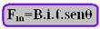
See the mathematical expression below that relates the intensities of these three quantities:
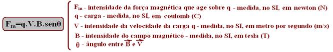
The mass m of the particle also has an influence, since if F m is the resulting force, F m = ma
R-B
03-(UFMG-MG)
Between the poles of the magnet the magnetic force, by the left hand rule, would be coming out of the sheet, but
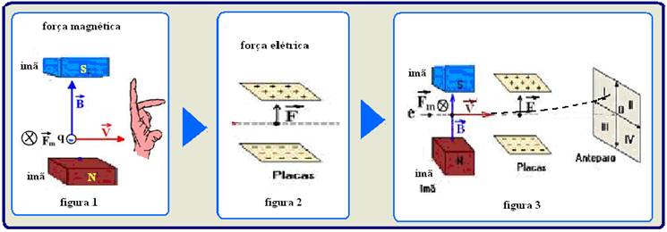
as the charge is negative it is penetrating and diverting the charge behind the sheet (figure 1) — when the negative charge passes between the plates it is diverted by the electric force upwards, attracted by the positive plate and repelled by the negative (figure 2) — so it deviates behind the sheet and upwards reaching region I — R- A
04-(UFMG-MG)
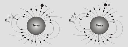
The magnetic force on a particle in a magnetic field has an intensity given by: F mag = |q| v B senθ, where θ is the angle between the vectors . ![]()
For the particle K — θ = 0° — senθ = 0 — F mag = 0 — this particle does not undergo deviation, as it is incident parallel to ![]() .
.
For the particle L — θ = 90° — senθ = 1 — F mag = |q| v B — the direction and sense of this force are given by the left-hand rule — the direction is perpendicular to the plane of the figure, going out if the charge is positive; going in if the charge is negative, as illustrated in the figures.
A- A
05-(UFMS-MS)
If you don’t know the theory, read it carefully — Consider a straight conductor of length ℓ carrying an electric current (free electrons with charge q, moving with speed ![]() inside the conductor, through its cross section). This straight conducting wire is immersed in a uniform magnetic field
inside the conductor, through its cross section). This straight conducting wire is immersed in a uniform magnetic field ![]() . Over each electric charge q that constitutes the electric current i, a
. Over each electric charge q that constitutes the electric current i, a
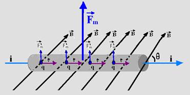
magnetic force provided by the expression F m ‘=qVBsenθ and adding the intensities of each force F m ‘ we obtain a resulting force F m =nF m ‘, where n is the number of charges that pass through the conducting wire in a time interval Δt — F m =nqVBsenθ — V=ΔS/Δt=ℓ/Δt — F m = nq ℓ/Δt.B.senθ — i=nq/Δt — F m =Biℓ.senθ
F m – intensity of the magnetic force acting on the wire – measured in newtons (N), in SI.
B – magnetic field intensity – measured in tesla (T), in SI.
i – electric current in the wire – measured in ampere (A), in SI.
θ – angle between the direction of B and i.
The direction and sense of ![]() is given by the left hand rule (see figure below) where the middle finger indicates the direction of
is given by the left hand rule (see figure below) where the middle finger indicates the direction of
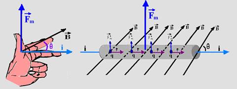
electric current i, since the conventional direction of the electric current is the same as the speed of positive charges.
In the exercise — Case (a) — F(a)=BiLsen45 0 =(√2/2).BiL — case (b) — F(b)=BiL.sen90 0 =BiL — case (c) — F(c)=BiLsen0 o =0 —
R-B
06-(UEL-PR)
Observe the figure below where the exercise situation is schematized and, as the weight force is vertical and downwards, the magnetic force must be vertical and upwards to be able to cancel the force.
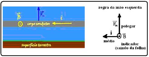
weight — using the left hand rule, the electric current should point to the left and the magnetic field should be perpendicular to the wire and coming out of the sheet — R- A
07-(PUC-RS)
When the heart muscle contracts, an electric current appears in the wire — in this case, i coming out of the plane of the page — the magnetic field ![]() is vertical and downward — left-hand rule — the
is vertical and downward — left-hand rule — the
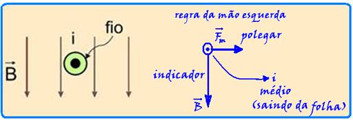
magnetic force ![]() will be horizontal and to the right — Fm=BiL (directly proportional to there) —
will be horizontal and to the right — Fm=BiL (directly proportional to there) —
A- A
08-(UFPEL-RS)
Read information below:
One of the practical processes for determining the direction and sense of the magnetic induction vector ![]() or magnetic field vector
or magnetic field vector ![]() is the right-hand rule. This sense
is the right-hand rule. This sense ![]() depends on the direction of the current that originates it.
depends on the direction of the current that originates it.
You place your thumb in the direction of the current with your hand flat (first figure), then
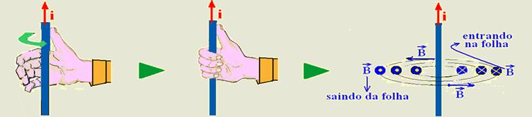
you close your hand n to grab the wire (second figure) and the direction of the “closed” hand is the direction of the vector ![]() (third figure). Note in the third figure that
(third figure). Note in the third figure that ![]() it is always tangent to the lines of induction at each point.
it is always tangent to the lines of induction at each point.
In the case of the exercise — By the right-hand rule the direction of ![]() is out of the page (leaving it) and by the mathematical expression B=μ.i/2πr, the intensity of B is inversely proportional to the distance r — R- A
is out of the page (leaving it) and by the mathematical expression B=μ.i/2πr, the intensity of B is inversely proportional to the distance r — R- A
09-(UFU-MG)
When no electric current passes through the wire, the compass needle indicates the magnetic north-south direction of the Earth — when electric current passes through the wire, another magnetic field arises due to the wire and the compass needle will indicate another position that is obtained by the vector sum of the two magnetic fields, that is, ![]() =
= ![]() +
+ ![]() — R- B
— R- B
10-(PUC-SP)
If you haven’t mastered the theory, here it is:
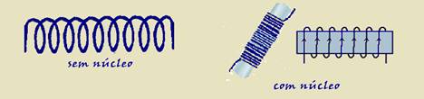
![]() A solenoid or long coil consists of a conductor wound with a very large number of equal turns, one next to the other, as shown in the figure below.
A solenoid or long coil consists of a conductor wound with a very large number of equal turns, one next to the other, as shown in the figure below.
![]() When the solenoid is traversed by electric current, it transforms into an artificial magnet (electromagnet) and the configuration of its induction lines is obtained by combining the configurations of each coil, which is equivalent to the configuration of the induction lines of a natural magnet.
When the solenoid is traversed by electric current, it transforms into an artificial magnet (electromagnet) and the configuration of its induction lines is obtained by combining the configurations of each coil, which is equivalent to the configuration of the induction lines of a natural magnet.
The direction of the induction lines in the solenoid is given by the right-hand rule applied in a
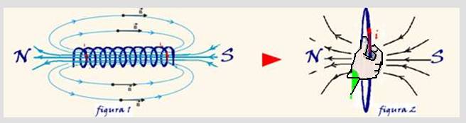
of its coils (figure 2) “thumb in the direction of the current ie you close your hand passing through the coil and in the direction of the closed hand is the direction of the induction lines of the magnetic field” and inside it the magnetic field is practically uniform (figure 1) and outside are lines that leave the north pole and reach the south pole.
![]() The lines of force of the magnetic field produced by a solenoid are identical to those of the magnetic field produced by a
The lines of force of the magnetic field produced by a solenoid are identical to those of the magnetic field produced by a
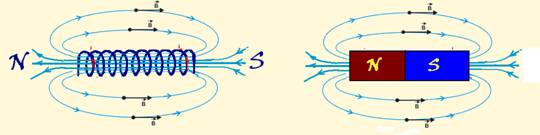
magnet. In practice, it makes no difference whether a magnetic field is produced by a magnet or by a solenoid.
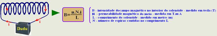
![]() Inside the solenoid the magnetic field is practically uniform and its intensity is constant and is:
Inside the solenoid the magnetic field is practically uniform and its intensity is constant and is:
In the case of exercise:
I- Using the right hand rule you can verify that it is correct.
II- False — magnet (artificial or natural) attracts iron regardless of polarity.
III- False — the magnetic induction vector inside the magnet is proportional to the electric current i which will increase (see formula above).
R-D
11-(UFAL-AL)
A- E — see resolution of the previous exercise
12-(FUVEST-SP)
The approach of the magnet causes a variation in the magnetic flux through the ring — according to Lenz’s Law, whenever there is a variation in the magnetic flux, an induced current appears in the ring — this current is in a direction that produces a polarity in the ring that tends to CANCEL the cause that gave rise to it, in this case, the movement of the magnet — as the north pole is being approached, a north pole will also appear on the face of the ring facing the magnet, generating a repulsive force between them.
R- And