Força Eletromotriz Induzida. Transformadores – Resolução EN
INDUCED ELECTROMOTIVE FORCE. TRANSFORMERS – RESOLUTION
Entrance exam exercises with commented solutions on
Induced Electromotive Force – Transformers
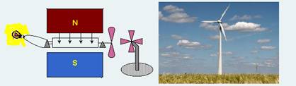
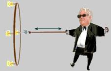
01-(UNIFESP-SP) The photo shows a battery-free flashlight, recently launched on the market. It works by transforming the kinetic energy supplied by the user into electrical energy – to do this, the user must shake it vigorously in the direction of its length. Since the inside of this flashlight is visible, one can see how it works: by shaking it, the user makes a cylindrical magnet pass through a coil back and forth. The movement of the magnet through the coil causes an induced current to appear in it, which runs through and lights the lamp. 
The physical principle on which this flashlight is based and the current induced in the coil are, respectively:
a) electromagnetic induction; alternating current.
b) electromagnetic induction; direct current.
c) Coulomb’s law; direct current.
d) Coulomb’s law; alternating current.
e) Ampere’s law; alternating or direct currents can be induced.
02-(UFPE-PE) The magnetic flux through the ring in the figure is 37.10 -3 Wb. When the current that produces this flux is interrupted, the flux drops to zero in the time interval of 1.0 ms.
Determine the magnitude of the average electromotive force induced in the ring, in volts.
03-(UFSC-SC) Wind energy can be an excellent option to compose the energy matrix of a nation like Brazil. A student built a model of a “wind” electric generator by placing a fan in front of blades connected to a coil with an area of 1.0.10 -3 m 2 , which is in a constant magnetic field of 2.0.10 -2 T.
The generator model is represented by the following diagram. Observe it and mark the CORRECT proposition(s).
(01) With the fan on and the coil rotating, the lamp shines, and the current generated is alternating.
(02) While the coil is rotating, the magnetic field generates a torque on it that opposes its rotational movement.
(04) Alternating currents are normally used in transmission lines, as they can be reduced or increased if we use transformers.
(08) Even without wind and with the coil still, we will have an induced electromotive force, as a constant field always generates an electromotive force on a coil.
(16) The magnitude of the magnetic flux in the loop varies between -2.10 -5 T m 2 and the maximum value of 2.10 -5 T m 2 .
04-(UFPE-PE) The graph shows the time dependence of a spatially magnetic field
uniform that passes through a square spiral with a side of 10 cm.
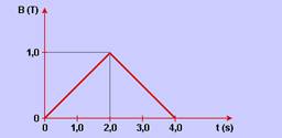
It is known that the electrical resistance of the wire from which the coil is formed is 0.2 ohm. Calculate the electrical current induced in the coil, in mA, between the instants t = 0 and t = 2.0 s.
05-(ITA-SP) When a metal bar moves in a magnetic field, its electrons move to one of the ends, causing an electrical polarization between them. In this way, a constant electric field is created inside the metal, generating a potential difference between the ends of the bar. Consider an uncharged metal bar, 2.0 m long, that moves at a constant speed of module v = 216 km/h in a horizontal plane (see figure).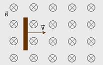
close to the Earth’s surface. A potential difference (ddp) of 3.0.10 -3 V is created between the ends of the bar, the value of the vertical component of the Earth’s magnetic induction field at that location is
a) 6.9.10 -6 T
b) 1.4.10 -5 T
c) 2.5.10 -5 T
d) 4, 2.10 -5 T
e) 5.0.10 -5 T
06-(UFPE-PR) A ring is in a region of space where there is a magnetic field density that varies with time. The magnetic field density is uniform throughout the region and ![]()
perpendicular to the plane of the ring. The graph shows the magnitude of ![]() as a function of time. Observing the graph, indicate the correct statement regarding the induced electromotive forces, ”a, ”b, ”c and ”d, during the respective time intervals a, b, c and d.
as a function of time. Observing the graph, indicate the correct statement regarding the induced electromotive forces, ”a, ”b, ”c and ”d, during the respective time intervals a, b, c and d.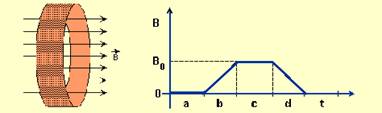
a) ε a = constant ≠ 0.
b) ε b = 0.
c) ε c = constant ≠ 0.
d) ε d = 0.
e) ε d = constant ≠ 0.
07-(UFSCAR-SP) A circular coil with an area of 1m2 is placed in a magnetic field. The field remains perpendicular to the plane of the coil, but its intensity decreases uniformly at a rate of 2T per second. Calculate the intensity of the current that circulates through the coil if its electrical resistance is 4Ω.
08-(UEG-GO) The figure below shows two circuits in which a conducting bar slides at the same speed « through the same uniform magnetic field and along a U-shaped wire. The parallel sides of the wire are separated by a distance 2L in circuit 1 and by L in circuit 2. The current induced in circuit 1 is in the counterclockwise direction. Judge the validity of the following statements.
I. The direction of the magnetic field is into the page.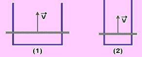
II. The direction of the induced current in circuit 2 is counterclockwise.
III. The emf induced in circuit 1 is equal to that in circuit 2.
Select the CORRECT alternative:
a) Only statements I and II are true.
b) Only statements I and III are true.
c) Only statements II and III are true.
d) All statements are true.
09-(UERJ-RJ) To produce the electrical energy necessary for its operation, the ship has an electric generator that provides a power of 16.8 MW. This generator , whose solenoid contains 10,000 turns with a radius of 2.0 m each, creates a magnetic field B with a module equal to 1.5.10 -2 T, perpendicular to the turns, which reduces to zero in the time interval of 5.10 -2 s.
a) The following diagram represents the generator. Knowing that its mass is 2.16.105 kg and that it is supported by twelve square supports with sides of 0.5 m, calculate the pressure, in N/m2 , exerted by it on the supports. (g=10m/ s2 )
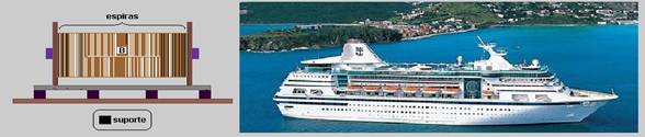
b) Determine the average induced electromotive force that is generated in the time interval in which the magnetic field reduces to zero.
10- (UFRN) At the end of his work day, Pedro Pedreiro calmly faces the darkness of the roads on his bicycle because, in order to travel at night more safely, he installed a dynamo on his bicycle that powers a 12V bulb. In a bicycle dynamo, the fixed part (stator) is made up of coils (coils), where the electric current is generated, and a moving part (rotor), where there is a permanent magnet, which rotates due to the contact of the rotor shaft with the bicycle tire. Based on the description above and with the help of knowledge of Physics, it can be stated that:
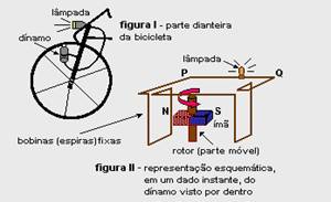
a) the energy per unit time emitted by the lamp shown in figure I does not depend on the speed of the bicycle.
b) at the instant represented in figure II, the correct direction of the induced electric current is from point Q to point P.
c) the conversion of mechanical energy into electrical energy occurs due to the temporal variation of the magnetic flux in the coils (figure II).
d) the angular speed of the rotor (figure II) must be equal to the angular speed of the bicycle tire (figure I) for the lamp to work.
11-(UFC–CE) Figure (a) shows a rectangular loop of 20 cm by 30 cm, containing an ideal ammeter A and a resistor R, whose resistance is 3.0 Ω. A uniform magnetic field, whose intensity B changes with time, as shown in figure (b), is applied perpendicular to the plane of the loop for 1.2 seconds. The current values, in amps, measured by the ammeter, corresponding to time intervals I, II and III shown in figure (b) are, respectively:
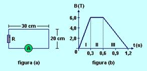
a) 0.5; 0 and 0.1.
b) 0.4; 0 and 0.2.
c) 0.3; 0.1 and 0.3.
d) 0.2; 0.1 and 0.4.
e) 0.1; 0.2 and 0.5.
12-(UFU–MG) A square coil with sides of 0.10 m and a total resistance of 20Ω is immersed in a magnetic field oriented perpendicular to the plane of the coil, as shown in the figure. The magnetic flux through the coil varies with time according to the graph presented. Based on this information, it is correct to state that:
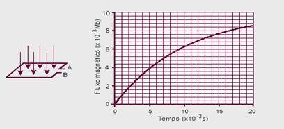
a) if the magnetic field varies only with time, its magnitude at instant t = 1.6.10 -2 s will be equal to 8T.
b) the emf induced between points A and B, between instants t = 0 set = 1.6.10 -2 s, will be 2 V.
c) according to Lenz’s Law, the electric current induced in the loop will circulate from B to A.
d) the electric current induced in the loop between instants t = 0 set = 1.6.10 -2 s will be 0.025 A.
13-(ITA-SP) A U-shaped coil is connected to a moving conductor AB. The assembly is subjected to a magnetic induction field, B = 4.0 T, perpendicular to the plane of the paper and oriented towards it. The width of the coil is, L = 2.0 cm
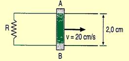
Determine the induced electromotive force and the conventional direction of the current, knowing that the speed AB is 20 cm/s.
14-(ITA-SP) A bicycle, with wheels measuring 60 cm in external diameter, has its speedometer composed of a magnet attached to spokes, 15 cm from the wheel axle, and a square coil measuring 25 mm2 in area, with 20 turns of metal wire, attached to the bicycle fork. 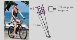
The magnet is capable of producing a magnetic induction field of 0.2 T across the entire area of the coil (see figure). With the bicycle traveling at 36 km/h, the maximum electromotive force generated by the coil is
a) 2 x 10 -5 V
b) 5 x 10 -3 V
c) 1 x 10 -2 V
d) 1 x 10 -1 V
e) 10V
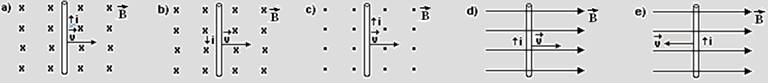
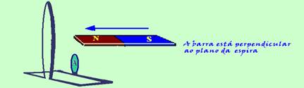
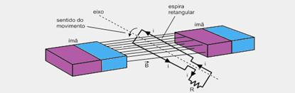
15-(UFSM-RS) The turbine driven by water is coupled to an electric generator . The figure that correctly represents the direction of the conventional current (i) in a segment of conductor that moves at speed , in a region of uniform magnetic field , is: ![]()
![]()
16-(UNICAMP-SP) The operating principle of metal detectors used in security checks is based on Faraday’s law of induction. The electromotive force induced by a variable magnetic field flow through a coil generates a current. If a piece of metal is placed near the coil, the value of the magnetic field will change, modifying the current in the coil. This variation can be detected and used to recognize the presence of a metallic body in its vicinity.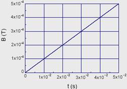
Consider that the magnetic field B passes perpendicularly through the loop and varies in time according to the figure. If the loop has a radius of 2 cm, what is the induced electromotive force?
17 – (UFBA) In a region where there is a uniform magnetic field B = 0.2T in the vertical direction,
a metal bar — of negligible mass, length L = 1 m and electrical resistance R = 0.5Ω — slides without friction, under the action of a weight, over parallel conductive rails of negligible resistance, as shown in the figure.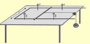
Knowing that the circuit formed by the bar and the rails is contained in a horizontal plane and that, after a few moments, the bar starts to move at constant speed, identify the origin of the force that balances the weight and, considering the mass M=40g and the acceleration of gravity g=10m/s2 , calculate the value of the constant speed.
18-(ITA-SP) The figure shows a circuit formed by a fixed bar FGHJ and a movable bar MN,
immersed in a magnetic field perpendicular to the plane of this circuit. Considering the friction between the bars to be negligible and also that the circuit is powered by a constant current generator I, what should happen to the movable bar MN?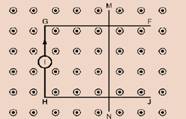
a) Stay in the same place.
b) Moves to the right at constant speed.
c) Moves to the left at constant speed.
d) Moves to the right with constant acceleration.
e) Moves to the left with constant acceleration.
19- (ITA-SP) A metal rod with a mass of 5.0 kg and a resistance of 2.0 Ω slides without friction
on two parallel bars 1.0 m apart, interconnected by a zero resistance conductor and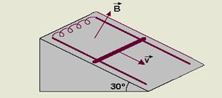
supported on a plane at 30° to the horizontal, as shown in the figure. Everything is immersed in a magnetic field B , perpendicular to the plane of movement, and the support bars have negligible resistance and friction.
Considering that after sliding for a certain time the speed of the rod remains constant at 2.0 m/s, indicate the value of the magnetic field. (g=10m/s 2 )
a) 25.0 T
b) 20.0 T
c) 15.0 T
d) 10.0 T
e) 5.0 T
20-(FUVEST-SP) An aluminum ring, suspended by an insulating wire, oscillates between the poles of a magnet , initially remaining in the plane perpendicular to the N-S axis and equidistant from the polar faces. The ring oscillates, entering and leaving the region between the poles, with a certain amplitude.
Under these conditions, without taking into account air resistance and other forms of mechanical friction, it can be stated that, over time,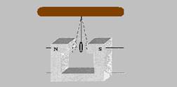
a) the amplitude of the ring’s oscillation decreases.
b) the amplitude of the ring’s oscillation increases.
c) the amplitude of the ring’s oscillation remains constant.
d) the ring is attracted to the North pole of the magnet and remains there.
e) the ring is attracted to the south pole of the magnet and remains there.
21-(UnB-DF) The magnet in the figure is establishing a flux Φ 1 = 0.3.10 -3 Wb. By quickly bringing the magnet closer to the coil, the flux becomes Φ 2 = 2.3.10 -3 Wb. Assuming that this variation occurred in a
time interval Δt=0.5s and the resistance of the loop is 1.0Ω, determine the current induced in the loop. Give your answer in milliamps.
22-(ITA-SP) A uniform magnetic induction field is applied perpendicularly to the plane of a circular loop with area A=0.5m2 , as shown in the figure. The vector varies with time as shown in the graph. ![]()
![]()
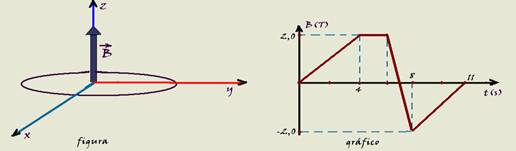
Sketch the induced electromagnetic force as a function of time, assuming that the electromotive force that coincides with the clockwise direction is positive, and that the one that coincides with the counterclockwise direction is negative. (Assume that the coil is viewed from above)
23-(UnB-DF) The graph below shows the magnitude of the magnetic field that passes through a coil with 100 turns as a function of time.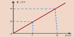
Knowing that the coils are square and have a side of 20 cm, calculate the electromotive force induced in the coil, if the magnetic field is given in tesla and the time in seconds. Give the answer in volts.
24-(UERJ-RJ) The magician passes a cane through a hoop, with a radius of 40 cm, containing small lamps, which light up and remain lit while the relative movement between the two objects is maintained. In reality, the cane is a magnet and the hoop is a circular metal coil. It can be assumed that the plane of the coil is kept perpendicular to the lines of magnetic induction during the relative movement. Considering 3 and assuming that the magnetic field varies from zero to 1.0T in 0.40 s, calculate the electromotive force induced in the coil. ![]()
![]()
25-(UERJ-RJ) The driver starts the car to begin his journey. The car’s ignition system has a set of spark plugs connected to the terminals of a coil with 30,000 circular turns. The average diameter of the turns is equal to 4.0 cm. This system,
when activated, it produces a variation in the magnetic field, ![]() , of 10 3 T in the coil, the field being
, of 10 3 T in the coil, the field being ![]() perpendicular to the plane of the coils. Establish the module of the resulting voltage between the coil terminals when the ignition system is activated.
perpendicular to the plane of the coils. Establish the module of the resulting voltage between the coil terminals when the ignition system is activated.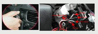
26-(Fazu-MG) An airplane, flying at an altitude of 10,000m, suffers a breakdown and falls, cutting the Earth’s magnetic field lines. Under these conditions, it is possible to measure, between the ends of the airplane’s wings:
a) an electric current
b) a magnetic field
c) a temperature difference
d) a mechanical compression
e) a potential difference
27-(UFB) The TAM Airbus A330-200 has a wingspan of 60 m (distance between the wingtips). It flies at 720 km/h and at a constant altitude, in a region where the vertical component of the Earth’s magnetic induction vector (Earth’s magnetic field) has a value of 5.10 -5 T. Calculate the potential difference (emf) induced between the wingtips.
28-(UFABC-SP) By rotating a coil inside a constant uniform magnetic field, it is subject to an induced electric current that varies according to the inclination of the coil inside this field.
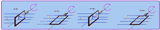
Knowing that the angular velocity of the coil is kept constant and that the sequence shown is completed in one cycle, sketch a graph of the intensity of the electric current i as a function of time t for the first 8s.
29-(FUVEST-SP) Is it possible to light an LED by moving a bar with your hands? To test this possibility, a young man uses a U-shaped electrical conductor, over which a bar M, also conductive, can be moved.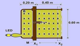
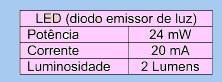
between positions X 1 and X 2 . This arrangement delimits a conductive loop, in which the LED is inserted, whose characteristics are indicated in the table alongside. The entire assembly is placed in a magnetic field B (perpendicular to the plane of this sheet and entering it), with an intensity of 1.1 T.
The young man, holding an insulating handle, must make the bar slide between X 1 and X 2 . To check under what conditions the LED would light up during the movement, estimate:
a) The voltage V, in volts, that must be produced at the LED terminals for it to light up according to its specifications.
b) The variation of the flux ΔΦ of the magnetic field through the loop, in the movement between X 1 and X 2 .
c) The time interval t, in s, during which the bar must be moved between the two positions, at constant speed, for the LED to light up.
NOTE AND ADOPT: The induced electromotive force is such that ε = – ΔΦ/Δt
30-(UNICAMP-SP) The clamp meter is an electric current meter, whose operating principle is based on the magnetic field produced by the current. To take a measurement, simply wrap the wire with the ammeter handle, as illustrated in the following figure.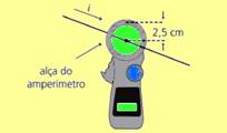
a) In the case of a long, straight wire through which a current i passes, the magnitude of the magnetic field produced at a distance r
from the center of the wire is given by B=μ o i /2π r, where μ o =4.π10 -7 T.m/A.. If the magnetic field at a point on the circular handle of the pliers in the figure is equal to 1.0.10 -5 T, what is the current that runs through the wire located in the center of the ammeter handle?
b) The handle of the pliers is composed of a coil with several turns, each with area A = 0.6 cm 2 . At a certain measurement, the magnetic field, which is perpendicular to the area of the turn, varies from zero to 5.0.10 -6 T in 2.0.10 -3 s. What is the induced electromotive force ε , in a turn? Faraday’s law of induction is given by: ε = -ΔΦ/Δt , where Φ is the magnetic flux, which, in this case, is the product of the magnetic field by the area of the turn.
31-(UFSM-RS) Electrical energy is transmitted at high voltages, but in homes, sockets provide low voltages.
Transformers are electromagnetic devices that, based on the law of ____________, change the value of electrical ____________ ____________.
Select the alternative that completes the gaps.
a) Faraday – voltage – alternating
b) Faraday – voltage – continuous
c) Ampere – voltage – alternating
d) Ampere – force – alternating
e) Ampere – force – continuous
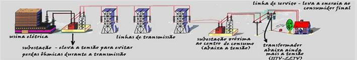
32-(UFSM-RS) Electric power generating plants produce _____ which allows, through a transformer , to increase the _____ and, thus, decrease the ______, in order to reduce energy losses due to the Joule effect in transmission lines.
Select the alternative that correctly fills in the gaps.
a) voltage – electric current – voltage
b) direct current – electric current – voltage
c) alternating current – voltage – electric current
d) direct current – voltage – electric current
e) alternating current – electric current – voltage
33-(UFSCAR-SP) At the end of the 19th century, a technological dispute over which electric current was most suitable for the transmission and distribution of electrical energy generated in power plants made clear the advantage of using alternating current over direct current. One of the decisive factors for this choice was the possibility of using transformers in the power grid.
electricity distribution. Transformers can increase or decrease the voltage supplied to them, allowing the adjustment of the values of the intensity of the transmitted current and reducing losses due to the Joule effect, BUT THEY ONLY WORK ON ALTERNATING CURRENT. The physical principle on which transformers operate and the characteristic of alternating current that satisfies this principle are, respectively,
a) conservation of charge and the oscillating motion of electric charge carriers.
b) electrostatic induction and the continuous movement of electric charge carriers.
c) electrostatic induction and the oscillating movement of electric charge carriers.
d) electromagnetic induction and the continuous movement of electric charge carriers.
e) electromagnetic induction and the oscillating movement of electric charge carriers.
34-(UFRN-RN) The residential landline telephone line is powered by direct current (DC) with a voltage of 45V and operates independently of the conventional electrical grid, which is alternating current (AC) with a voltage of 220V. Due to a frequent power outage on the conventional line in his home, Joãozinho, a high school student, thought about making a voltage step-up transformer to use in the lamp on his study table. His idea is to take power from the telephone socket (which is prohibited by law) and use it in an emergency situation.
It can be said that Joãozinho’s objective
a) will be achieved, but, according to Faraday’s law, the luminaire’s efficiency will drop slightly compared to that obtained when the luminaire is connected to the conventional network.
b) will only be achieved if the telephone line has a voltage of at least 110 V.
c) will not be achieved, due to the impossibility of increasing direct voltage to alternating voltage with just a transformer.
d) will not be achieved, because voltage can only be lowered, not raised.
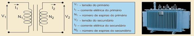
35-(UFRS-RS) The phenomenon of electromagnetic induction makes it possible to explain the functioning of several devices, including the transformer, which is an electrical equipment that appeared at the beginning of the 19th century, as a result of the union between the work of scientists and engineers, and is today an essential component in electrical and electronic technology.
Used when there is a need to increase or decrease electrical voltage, the transformer consists of an iron core and two coils, as illustrated in the following figure. One of the coils (called the primary) has N 1 turns and the voltage U 1 is applied to it , while the other (called the secondary) has N 2 turns and supplies the voltage U 2 .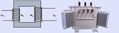
About the transformer , it is correct to state:
a) It is used to modify the voltage in both direct current and alternating current systems.
b) The voltage U 2 only appears when the flux of the magnetic field produced by the primary is constant.
c) In an ideal transformer, the power supplied to the primary is different from the power supplied by the secondary.
d) When the number of turns N 1 is less than N 2 , the current in the secondary is greater than the current in the primary.
e) When the number of turns N 1 is less than N 2 , the voltage U 2 will be greater than the applied voltage U 1 .
36-(UFSM-RS) An old gasoline truck needs high voltage in the spark plugs to produce the sparks that start the process of burning this fuel in the combustion chambers, and this voltage is obtained by means of an induction coil. The transformation from low voltage to high voltage is based on the law of
a) Coulomb.
b) Ohm.
c) Kirchhoff.
d) Ampere.
e) Faraday.
37-(UFRS-RS) Select the alternative that correctly fills in the gaps in the text below.
Materials with special magnetic properties play a very important role in modern technology. Among their many applications, we can mention magnetic recording and reading, used in magnetic tapes and computer disks.
The basic idea behind magnetic reading is the following: variations in the intensity of fields ………., produced by the tape or disk in motion, induce ………. in a coil in the reading head, giving rise to signals that are then amplified.
a) magnetic – magnetization
b) magnetic – electric currents
c) electric – electric currents
d) electrical – magnetization
e) electric – electric charges
38-(UEPG-PR) Regarding an ideal transformer in which the number of turns of the secondary winding is smaller than that of the primary winding, indicate what is correct.
01) The electrical power at the input of the primary winding of this transformer is equal to the electrical power at the output of the secondary winding.
02) If we connect the primary winding terminals to a 12 V battery, we will have a lower ddp in the secondary winding.
04) The energy in the primary winding is equal to the energy in the secondary winding, characterizing the principle of conservation of energy.
08) The currents in the primary and secondary windings of this transformer are equal.
16) The transfer of power from the primary winding to the secondary winding does not occur by induction.
39-(UNESP-SP) The figure represents one of Faraday’s experiments that illustrate electromagnetic induction, in which ε is a constant voltage battery, K is a key, B 1 and B 2 are two
coils wound on a soft iron core and G is a galvanometer connected to the terminals of B 2 which, with the pointer in the central position, indicates an electric current of zero intensity.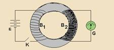
When switch K is turned on, the galvanometer pointer moves to the right and
a) It remains this way until the key is turned off, when the pointer moves to the left for a few moments and returns to the central position.
b) it then returns to the central position and remains there until the key is turned off, when the pointer moves to the left for a few moments and returns to the central position.
c) it then returns to the central position and remains there until the key is turned off, when the pointer moves to the right again for a few moments and returns to the central position.
d) to the left with an oscillation of constant frequency and amplitude and remains so until the switch is turned off, when the pointer returns to the central position.
e) to the left with an oscillation whose frequency and amplitude are continuously reduced until the switch is turned off, when the pointer returns to the central position.
40-(UFPR-PR) It is known that in a transformer there is not necessarily an electrical connection between the conductor of the primary winding and that of the secondary winding. However, electrical energy is transmitted from the primary to the secondary. Based on these facts and knowledge about electromagnetism, it is correct to state: 
(01) The electric current of the secondary winding does not influence the operation of the primary.
(02) The transformer only works with variable electrical current.
(04) It is the variation in the flux of the magnetic field in the windings that allows the transmission of electrical energy.
(08) The potential difference at the secondary winding terminals is always less than the potential difference at the primary winding terminals.
(16) The electric current is always the same in the primary and secondary windings.
41-(ITA-SP) Consider the transformer in the figure, where Vp is the voltage in the primary, Vs is the voltage in the secondary, R, a resistor , N 1 and N 2 are the number of turns in the primary and secondary, respectively, and S a switch. 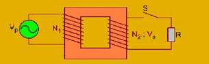
When the switch is closed, what should be the current Ip in the primary?
42-(UERJ-RJ) The supermarket has an electrical energy transformer that operates with a voltage of 8,800 V in the primary winding and voltages of 120 V and 220 V, respectively, in the
secondary windings 1 and 2. Consider that the voltage values are effective and that the transformer is ideal.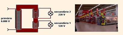
a) Determine the relationship between the number of turns in the primary and secondary windings 2.
b) Knowing that the power in the primary winding is 81,000 W and that the current in secondary 2 is 150 A, calculate the electric current in secondary winding 1.
Consider that the voltage values are effective and that the transformer is ideal.
43-(PUC-RS) In a transformer with negligible energy losses, the effective values of the current and voltage, in the primary, are respectively 2.00A and 80.0V, and in the secondary, the effective value of the current is 40.0A. Therefore, the quotient between the number of turns in the primary and the number of turns in the secondary, and the voltage in the secondary are, respectively,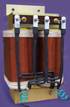
a) 40 and 40.0 V
b) 40 and 20.0 V
c) 20 and 20.0 V
d) 20 and 4.0 V
e) 10 and 2.0V
44- (UFSC-SC)

Pedrinho, after a Physics class, decided to experimentally verify what he had studied so far. For this experiment, he used a coil with 50 turns, a magnet attached to a support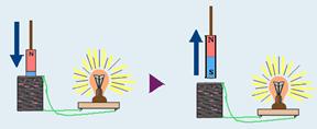
non-conducting and a 5 W incandescent bulb. The experiment consisted of moving the magnet in and out of the coil repeatedly. When the
experiment, Pedrinho made some observations, which are listed in the form of propositions.
Select the CORRECT proposition(s).
01) The magnitude of the electromotive force induced in the coil is directly proportional to the variation in magnetic flux as a function of distance.
02) It is difficult to move the magnet inside the coil, because the magnetic field of each coil offers resistance to the movement of the magnet. This is explained by Lenz’s Law.
04) If the current in the lamp is 2 A, the electromotive force induced in each turn of the coil is 0.05 V.
08) The frequency of the magnet ‘s movement inside the coil does not interfere with the lamp’s brightness.
16) For there to be an induced current in the coil, the circuit must be closed.
32) The work done to move the magnet in and out of the coil is entirely transformed into light energy in the lamp.
45- (UFOP-MG)

A transformer has the following nominal values: 110 V, 220 V and 2200 W.
Knowing that the winding whose terminals indicate 110 V has 250 turns, determine: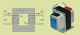
a) the number of turns of the winding corresponding to the electromotive force of 220 V;
b) the intensity of the current at each terminal when this transformer is used to connect a television, with nominal values of 220 V and 880 W, to a socket that supplies 110 V;
c) the maximum current intensity in each terminal.
46-(UFOP-MG)

To drain the electrical energy produced by its turbines, the Itaipu hydroelectric plant raises the output voltage to approximately 700,000 V. In your home, the sockets have a voltage of 127 V and/or 220 V. The equipment that performs this task
raising and lowering the voltage is the transformer . It is correct to state that
a) the operating principle of a transformer requires that the voltage/current be continuous.
b) the operating principle of a transformer requires that the voltage/current be alternating.
c) the transformer will work both in a network with alternating voltage/current and in one with direct voltage/current.
d) the transformer will work when, in the primary winding, there is a direct voltage/current and, in the secondary, an alternating voltage/current.
47-(UFT-TO) Regarding the phenomenon of electromagnetic induction:

I. It was discovered experimentally by M. Faraday
II. An electromotive force (emf) is always induced in a closed conducting loop when the magnetic flux through it varies.
III. The emf induced in this loop causes the appearance of an induced current.
We can say that:
a) None of the statements are correct.
b) Only statement I is correct.
c) Only statements I and II are correct.
d) Only statements I and III are correct.
e) All statements are correct.
48-(UDESC-SC)

The figure below shows a square coil with a side of 10.0 cm, located inside a uniform magnetic field B, perpendicular to the plane of the paper and directed into the paper, whose intensity is 0.50 Weber/m2 . The plane formed by the coil is parallel to the paper. When the magnetic field has its direction completely reversed, an induced electromotive force of 5.0 V appears in the coil.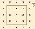
The average time interval used to completely reverse the direction of the magnetic field, in this case, is:
a) 1.0.10 -4 s
b) 1.0.10 -3 s
c) 2.0.10 -3 s
d) 10 s
e) zero
49-(CEFET-MG)

The figure below represents the diagram of a transformer used to increase or decrease the
electrical voltage supplied to a circuit. Regarding the operation of this transformer, if ________, then ____________.
The option that correctly completes the gaps above is:
a) V 1 = V 2 , i 1 < i 2 .
b) V 1 > V 2 , i 1 > i 2 .
c) V 1 > V 2 , N 1 > N 2 .
d) V 1 = V 2 , N 1 < N 2 .
50-(ENEM-MEC)

There are several types of treatments for brain diseases that require stimulating parts of the brain with electrical currents. Electrodes are inserted into the brain to generate small
currents in specific areas. To eliminate the need to insert electrodes into the brain, an alternative is to use coils that, placed outside the head, are capable of inducing electrical currents in the brain tissue.
For the treatment of brain pathologies with coils to be carried out satisfactorily, it is necessary that
a) there is a large number of turns in the coils, which reduces the induced voltage.
b) the magnetic field created by the coils is constant, so that there is electromagnetic induction.
c) it is observed that the intensity of the induced currents depends on the intensity of the current in the coils.
d) the current in the coils is continuous, so that the magnetic field can be of great intensity.
e) the magnetic field directs the electric current from the coils into the patient’s brain.
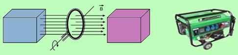
51-(UNESP-SP)

An electromagnetic generator consists of a coil with cross-sectional area S, which rotates at angular velocity w inside a uniform magnetic field of intensity B. As the coil rotates, the magnetic flux ф that passes through it varies according to the expression ф (t) = BScoswt where t is time, producing an electromotive force at the terminals of the electromagnetic generator, the direction of which reverses as the coil rotates. Thus, the current in resistor R, the direction of which reverses with each half turn, is called alternating current.
Consider a coil with a cross-section of 10 cm 2 , rotating at a rate of 20 turns per second, inside a magnetic field with an intensity equal to 2.10 -5 T.
Plot the graph of the magnetic flux ф (t) that passes through the loop as a function of time, during a period (T) indicating the values of the magnetic flux at instants T/4, T/2, 3T/4 and T.
52-(UFPR-PR)

One way to generate electrical currents is to transform mechanical energy into electrical energy through an electrical generator. In a simplified situation, there are magnets to produce the magnetic field and a coil formed by 10 circular coils with a diameter of 10 cm assembled as shown in the figure below. The coil is attached to an axis that passes through its diameter and rotates at a constant speed of 2 revolutions per second. The coil has two terminals that allow the electrical energy generated to be used. At a given moment, the magnetic field lines cross the plane of the coils perpendicularly and the magnetic flux is maximum; after the coil rotates 90° around the axis, this flux is zero.
Consider that in the region of the coil the magnetic field is uniform, with a module equal to 0.01 T and oriented as indicated in the figure. Determine the average electromotive force induced in the coil when rotating 90° from the situation of maximum flux.
53-(UFSC-SC)

One of the fundamental components for good sound quality is the speaker, which basically consists of a cone (usually made of cardboard), a coil and a permanent magnet, as
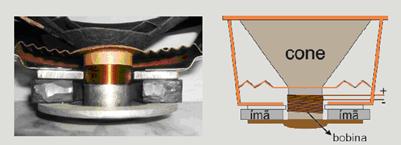
shown in the figures below.
Regarding how the speaker works, select the CORRECT statement(s).
01. The intensity of the magnetic field created by the coil depends solely on the number of turns.
02. The movement of the speaker cone is a consequence of Lenz’s law.
04. The vibration of the cone creates regions of high and low pressure in the air, which propagate in the form of transverse waves.
08. The pitch of the sound reproduced by the speaker depends on the frequency of the electrical signal sent by the stereo.
16. The intensity of the sound wave reproduced by the speaker is proportional to the intensity of the electric current that runs through the coil.
32. The electric current sent to the speaker passes through the coil, generating a magnetic field that interacts with the permanent magnet, causing the cone to move in the axial direction of the coil.
54-(UFSC-SC)

The magnetic field B through a single loop with a diameter of 80.0/√π cm and a resistance of 8.0 Ω varies with time, as shown in the graph below.
01. The induced electromotive force is maximum in the time interval between t = 4 sep = 5 s.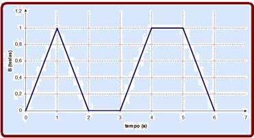
02. The electromotive force induced in the interval between t = 0 s and t = 1 s is 1.0 V.
04. The electromotive force induced in the interval between t = 1 set = 2 s is – 0.16 V.
08. The induced current in the interval between t = 5 sep = 6 s is 0.02 A.
16. The graph of the magnetic flux through the loop can be drawn from the graph of B as a function of t.
32. The electromotive force can be calculated based on Ampère’s law.
55-(IFNMG-MG)

Among many other contributions to Theoretical Physics, Einstein was notable for proposing thought experiments (from the German expression Gedankenexperiment). One of these, illustrated in
figure below describes the situation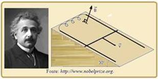
physics in which a metal rod, whose mass is 5.0 kg, having an electrical resistance of 2.0 Ω, slides without friction over two parallel bars separated by a distance of 1.0 m from each other. The bars are interconnected by a conductor of zero resistance and supported on a plane inclined at 30º to the horizontal. This assembly is in a vacuum and immersed in a magnetic induction field ![]() , perpendicular to the plane of movement. Considering that, after sliding for some time, the speed of the rod remains constant and equal to 2.0 m/s, the value of the module of B, expressed in tesla, is correctly presented in the alternative:
, perpendicular to the plane of movement. Considering that, after sliding for some time, the speed of the rod remains constant and equal to 2.0 m/s, the value of the module of B, expressed in tesla, is correctly presented in the alternative:
![]()
56-(UNIOESTE-PR)

The oscillator shown in the figure below consists of a metal bar of mass M and resistivity ρ, whose terminals are “r” and “s”, and an insulating spring with spring constant “k”. This system is in contact and slides without friction on a horizontal rail, made of the same material as the bar, in the shape of a “C”. The “x”s denote a region of space where there is a uniform magnetic field, of magnitude B, perpendicular to the plane containing the rails. The numbered vertical arrows indicate some positions. The effects of friction with the air are negligible.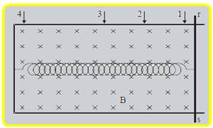
At time t = 0 the oscillator is released at point (1) from rest and begins to move. As for
amplitude (A) of the movement performed and the tension (V rs ) measured between “r” and “s”, and it is correct to state that
A. A decreases over time and V rs has a greater magnitude when passing through (1).
B. A decreases with time and V rs has a greater magnitude when passing through (2)
C. A decreases over time and V rs has a greater magnitude when passing through (3).
D. A remains constant and V rs has a greater magnitude when passing through (2).
E. A remains constant and V rs is always zero.
57-(AFA)

The figure below shows a magnet oscillating near a circular coil, made of conductive material, connected to a lamp.
The electrical resistance of the coil, connecting wires and lamp assembly is equal to R and the magnet oscillates in SHM with a period equal to T. In these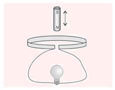
conditions, the number of electrons that pass through the lamp filament during each approach of the magnet
a) is directly proportional to T.
b) is directly proportional to T 2 .
c) is inversely proportional to T.
d) does not depend on T.