Resolution – Magnetic Force EN
RESOLUTION – MAGNETIC FORCE
Exercises with commented resolution on
Magnetic force on a straight conductor
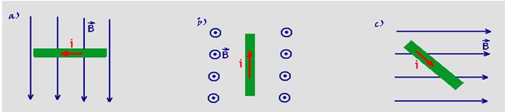
01-(UFB) Represent the magnetic force that acts on each straight conductor, carried by electric current and immersed inside a uniform magnetic field, in the cases:
02-(UFMS-MS) A conducting wire of length L, carrying a current of intensity i, is immersed in a uniform magnetic field B. The figure below shows three different positions of the wire (a), (b) and (c), in relation to the direction of the magnetic field. Given that F(a), F(b) and F(c) are the intensities of the magnetic forces produced in the wire, in the respective positions, it is correct to state that:
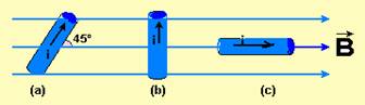
a) F(a) > F(b) > F(c).
b) F(b) > F(a) > F(c).
c) F(a) > F(c) > F(b).
d) F(c) > F(b) > F(a).
e) F(a) = F(b) = F(c).
03-(UFB) A conducting wire is bent to form a rectangle ABCD (rectangular loop), which can rotate freely around axis e. Let i be the constant current intensity that runs through the loop in the direction indicated in the figure.
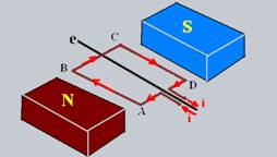
Represent the magnetic forces acting on each side of the loop and determine their intensities considering: L AD = L BC = 0.1 m; L AB = L CD = 0.2 m; i = 10 A, B = 2.0.10 -3 T and the angle between B and i as being θ = 90 o for sides AB and CD and θ = 0 o for sides BC and AD.
04-(UFRGS) In the figure below, a flexible conductive wire is in the presence of a constant and uniform magnetic field perpendicular to the plane of the page. In the absence of electric current, the wire remains in position B. When the wire is traversed by a certain stationary electric current, it assumes position A.
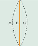
For the wire to assume position C, it is necessary
a) reverse the direction of the current and the applied field.
b) reverse the direction of the current or reverse the direction of the field.
c) slowly turn off the field.
d) slowly turn off the current.
e) slowly turn off the field and current.
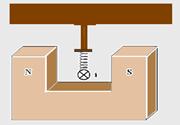
05-(UFB) The conductive metal bar PQ is in equilibrium and is traversed by the current i indicated in the figure. Identify the poles
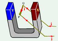
north and south of the magnet.
06-(UE-PB) A physics teacher decides to do an electromagnetism experiment that aims to determine the value of the magnetic field between the poles of a magnet. To do this, he uses a magnet and a battery that supplies 4.8V to a cylindrical AC conductor with a mass of 5g, a length of 10cm and an electrical resistance of 0.10Ω. When the battery is connected to the circuit shown in the figure, the cylindrical conductor remains suspended in equilibrium.
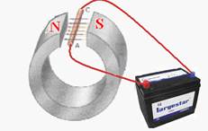
Considering that the field lines are perpendicular to the conductor, that the electrical resistance of the wires is 0.02Ω, that the mass of the wires is negligible and adopting g=10m/s2 , the professor concluded that the magnetic field, in tesla, has a value equal to:
![]()
07-(UFPE-PE) A wire MN, 40 cm long and with a mass of 30 g, is suspended horizontally by an ideal spring with an elastic constant k = 10 N/m. The assembly is in a region of uniform magnetic field B = 0.1 Wb/m2, as shown in the figure.
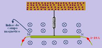
When the current in the wire is 10 A, directed from N to M, a magnetic force will act vertically downward on the wire. Determine the total elongation, due to the magnetic force and the gravitational force, suffered by the spring, in cm.
08-(UNICAMP-SP) A rigid conductive wire of 200 g and 20 cm in length is connected to the rest of the circuit by means of frictionless sliding contacts, as shown in the figure.
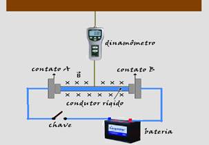
The plane of the figure is vertical. Initially the switch is open. The conducting wire is attached to a dynamometer and is in a region with a magnetic field of 1.0 T, entering perpendicularly into the plane of the figure: (consider g = 10 m/s 2 )
a) calculate the force measured by the dynamometer with the switch open, with the wire in balance.
b) determine the direction and intensity of the electric current in the circuit after the switch is closed, knowing that the dynamometer now indicates a reading of zero.
c) calculate the battery voltage knowing that the total resistance of the circuit is 6.0Ω.
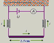
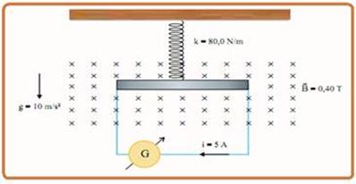
09 – (UFG–GO) To measure the intensity of a uniform magnetic field, the apparatus illustrated in the figure is used. The conducting wire is 2.5 cm long; the springs, which conduct electricity, have a spring constant of 5.0 N/m. When the electrical voltage is off, the springs present a deformation of 2.0 mm. With the voltage adjusted to produce a current of 1.0 A, the springs return to their natural state. Given that the magnetic field is perpendicular to the plane of the figure, determine its magnitude and direction. Neglect the effects of the current and the field on the springs.
10-(UEL-PR) “Japanese magnetic train breaks its own speed record (from Agência Lusa) – A Japanese magnetically levitating train, known as “Maglev”, broke its own speed record today by reaching 560 km/h during a test run.

via. The five-car train MLX01, whose previous record of 552 km/h was reached in April 1999 with 13 people on board, reached its new mark without carrying passengers. The Japanese train is slightly suspended from the track by the action of magnets, which eliminates the reduction in speed caused by friction with the rails.” (Available: http:www1.folha.uol.com.br/folha/ciencia Accessed on: September 13, 2004).
It is possible to leave a conducting body suspended, creating a magnetic force that is opposite to the gravitational force acting on it. To do this, the body must be immersed in a magnetic field and an electric current must pass through it. Consider a straight conducting wire as a horizontal line on this sheet of paper that you are reading, which should be considered as being positioned with its plane parallel to the Earth’s surface and in front of the reader. What should be the orientations of the magnetic field and the electric current, so that the resulting magnetic force is in the same direction and opposite to the gravitational force acting on the wire? Ignore the connections of the wire to the source of electric current.
a) The current should point to the left along the wire, and the magnetic field should be perpendicular to the wire, pointing towards the reader.
b) The current should point to the left along the wire, and the magnetic field should be parallel to the wire, pointing to the right.
c) The current should point to the right along the wire, and the magnetic field should be perpendicular to the wire, pointing out of the plane of the foil.
d) The current should point to the right along the wire, and the magnetic field should be parallel to the wire, pointing to the right.
e) The current should point to the left along the wire, and the magnetic field should be perpendicular to the wire, pointing into the plane of the foil.
11-(UNIFESP-SP) In the gridded region of the figure there is a uniform magnetic field, perpendicular to the plane of the grid and penetrating the plane of the figure. Part of a rigid circuit also passes through it, as illustrated in the figure.
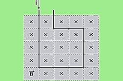
The edge of each square cell of the quadrilateral has length u, and an electric current of intensity i passes through the wire. Analyzing the magnetic force acting on each element of length u of the circuit wire, coinciding with the edge of the square cells, the intensity of the resulting magnetic force on the part of the circuit exposed to field B is:
![]()
12-(FUVEST-SP) To estimate the intensity of a uniform and horizontal magnetic field Bo , a rigid conductive wire is used, bent with the shape and dimensions indicated in the figure, supported on fixed supports, and allowed to rotate freely around the axis OO’. This arrangement works as a “balance for electromagnetic forces”. The wire is connected to a generator, adjusted so that the direct current supplied is always i = 2.0 A, and two small switches, A and C, when activated, establish different paths for the current. Initially, with the generator turned off, the wire remains in equilibrium in the horizontal position. When the generator is turned on, with switch A open and C closed, it is necessary to hang a small mass M 1 = 0.008 kg, in the middle of the segment P 3 – P 4 , to reestablish balance and keep the wire in the horizontal position.
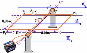
a) Determine the intensity of the electromagnetic force F 1 , in newtons, that acts on the segment P 3 P 4 of the wire, when the generator is turned on with switch A open and C closed.
b) Estimate the intensity of the magnetic field Bo , in teslas.
c) Estimate the mass M 2 , in kg, required to rebalance the wire horizontally when switch A is closed and switch C is open. Indicate where this mass should be placed, taking into account that mass M 1 has been removed.
The ends P 1 , P 2 , P 3 and P 4 are always in the same plane.
13-(UFC-CE) In the following figure, the main circuit is formed by a battery (zero internal resistance and electromotive force E), two conductive springs (each with spring constant k = 2 N/m and electrical resistance R = 0.05 Ω), a conductive bar of length L = 30 cm and negligible electrical resistance. The springs are at their natural lengths (without deformation). A magnetic field of module B = 0.01 T, perpendicular to the plane of the figure and pointing into the page, is present in the region of the bar.
There is also another insulating bar, connected to a conductive tip, fixed to the upper branch of the main circuit. The mass of the insulating bar is negligible. A lamp of resistance r and a battery of electromotive force E’ make up the attached circuit (see the following figure). The height between the conductive tip and the upper branch of the attached circuit is h = 3 cm.
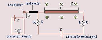
Select the alternative that contains the minimum value of the electromotive force ε in the main circuit, so that the lamp in the attached circuit is traversed by an electric current (disregard any gravitational effects).
![]()
14-(PUC-RS) Solve the question based on the following information.
The heart muscle undergoes periodic contractions, which generate small differences in potential, or electrical tensions, between certain points in the body.
Measuring these voltages provides important information about the functioning of the heart. One way to take these measurements is through an instrument called a wire electrocardiograph.

This instrument consists of a magnet that produces an intense magnetic field through which a thin, flexible wire passes. During the examination, electrodes are positioned at specific points on the body and connected to the wire. When the heart muscle contracts, a voltage arises between these electrodes and an electric current runs through the wire. Using a simplified model, the positioning of the straight wire in the uniform magnetic field of the electrocardiograph magnet can be represented as shown in the figure below, perpendicular to the plane of the page, and with the direction of the current leaving the plane of the page.

Based on this information, it can be said that when the heart muscle contracts, the wire undergoes a deflection
a) lateral and directly proportional to the current that runs through it.
b) laterally and inversely proportional to the intensity of the magnetic field in which it is placed.
c) vertical and inversely proportional to the voltage between the electrodes.
d) lateral and directly proportional to the electrical resistance of the wire.
e) vertical and directly proportional to the length of the wire.
(IFET-MG) The following statement refers to questions 15 and 16

The figure below shows a region where there is a uniform magnetic field , with a module equal to 5.0.10 -1 T, located between the poles of a magnet. In this region, there is an ideal spring , with an elastic constant k equal to 2.0.10 2 N/m, attached to the ceiling, which supports in its ![]()
end a cylindrical, conductive and straight wire, of length L equal to 2.0 m and mass M equal to 6.0.10 2 g. The wire is traversed by a direct current i, the direction of which is indicated by the symbol . ![]()
15-(IFET-MG)

Observing the figure above, we can conclude that the magnetic force acting on the wire will point
a) vertically downwards
b) vertically upwards
c) perpendicular to the plane of the paper, moving away from the reader
d) perpendicular to the plane of the paper, approaching the reader
e) horizontally to the right
16-(IFET-MG)

Assuming that the system is in equilibrium and adopting the acceleration of gravity g equal to 10 m/s 2 , the value of the deformation x suffered by the spring when the current i is equal to 4.0.10 -1 A is, in module, equal to
![]()
17-(UNIFESP-SP)

A spring of negligible mass is attached to the ceiling of a room and its other end is tied to the center of a homogeneous, horizontal metal bar that is 50 cm long and has a mass of 500 g. The metal bar, which can move in a vertical plane, has an ohmic resistance of 5 Ω and is connected by conducting wires of negligible mass to a direct current generator G with an internal ohmic resistance of 5 Ω and supported on a horizontal table. The bar-spring system is in a plane perpendicular to a horizontal magnetic field B, whose field lines penetrate this plane, as shown in the figure.
Determine:
a) the electromotive force, in volts, produced by the generator and the electrical power dissipated by the metal bar, in watts.
b) the deformation, in meters, suffered by the spring to keep the bar-spring system in mechanical equilibrium. Assume that the electrical wires are not subject to mechanical tension, that is, stretched.