Magnetic Flux – EN Resolution
MAGNETIC FLUX – RESOLUTION
Commented resolution of entrance exam exercises on
Magnetic Flux – Electromagnetic Induction – Direction of the induced electric current
01 – R- D — See theory
02- R- E — see theory
03- The only case in which there will be no variation in magnetic flux inside the ring is alternative C — R- C
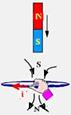
04- The south pole of the magnet is approaching the coil — the coil will create a south pole on its upper face in an attempt to repel the magnet — using the right-hand rule, the electric current induced in the coil corresponds to that of alternative A — R- A
05 – The north pole of the magnet is approaching the coil — the coil will create a north pole on its upper face in an attempt to repel the magnet — using the right-hand rule, the electric current induced in the coil corresponds to that in alternative 4 — R- D
06- I. Correct — for there to be induced electric current, there must be relative movement between them and of course a variation in magnetic flux.
II. Correct — there will only be induced electric current if there is a variation in magnetic flux.
III. False — it does depend — approach in one direction and distance in the opposite direction
R-C
07- When the magnet is approaching it tends to be repelled (vertically and upwards) — when the magnet is moving away it tends to be attracted (vertically and upwards) — R- C
08- R- A
09- The only alternative that causes a variation in the magnetic flux inside the coil is D — R- D
10- As the magnetic field originated by each wire is provided by B=μi/2πd, at each point between the wires the magnetic field is constant (i constant), there is no variation in magnetic flux over time and, consequently, no induced electric current arises — R- C ![]()
11- By the right-hand rule, coil I creates a vertical and upward magnetic field in the region where coil II is located, which is increasing — if it is increasing, an induced magnetic flux will appear in coil II, which will tend to prevent this increase, that is, vertical and downward — applying the right-hand rule in II with the vertical and downward flux, the current i 2 should have the opposite direction to that of i 1 — R- D
12- As there is no friction, the magnet will always be descending, varying the magnetic flux inside the coil, causing an induced electric current to appear in it and consequently a potential difference also induced in the voltmeter — R-C
13- It begins to penetrate the magnetic field until it penetrates completely, with the magnetic flux increasing, with the current in one direction (between 2a and 3a) — completely within the magnetic field there is no variation in flux, zero current (between 3a and 4a) — it begins to leave the magnetic field until it leaves completely, with the magnetic flux decreasing, with current in another direction (between 4a and 5a) — R- E .
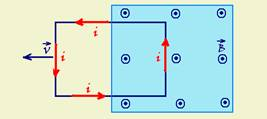
14- a) When it is entering the magnetic field, the magnetic flux inside it is increasing and the coil must generate a magnetic flux that tends to prevent this growth, creating a magnetic field in the opposite direction, that is, from top to bottom and, applying the right-hand rule, the current seen by the observer will be in the clockwise direction.
b) there is no variation in flux and the current is zero.
c) When it is leaving the magnetic field, the magnetic flux inside it is decreasing and the coil must generate a magnetic flux that tends to prevent this decrease, creating a magnetic field in the same direction, that is, from bottom to top and, applying the right-hand rule, the current seen by the observer will be in the counterclockwise direction.
15- By the right-hand rule, the wire creates a magnetic field in the region where the coil is located that is perpendicular to the sheet and penetrates it — for the current in the coil to be in the clockwise direction, the induced flux must also be penetrating the plane of the coil, which only occurs if the coil is moving away (magnetic flux inside the coil decreasing) — R- E
16- Only in regions I (varying, increasing magnetic flux) and III (varying, decreasing magnetic flux) — R- C
17- I. False — the intensity of the induced electric current is independent of the polarity of the magnets.
II. True — the coil, when rotating, varies the magnetic flux that passes through it.
III. False — the faster the coil rotates, the greater the variation in the magnetic flux that passes through it and, consequently, the greater the current i.
R-B
18- Intensity at any point of the wire B=μi/2πd — situation 1 – any point of the loop always maintains the same distance from the wire, therefore B is the same and there is no variation in flux or induced current — situation 2 – note in the equation that d is inversely proportional to B and, as d is increasing, B is decreasing, thus creating a variation in magnetic flux and consequently an induced electric current — situation 3 – as d is the same at all points inside the loop, B does not vary and neither does the magnetic flux – no induced electric current arises — R-C ![]()
19- a) Using the right-hand rule, for one turn, you determine the polarities of the solenoid
(figure 1) — the current induced in the coil must oppose the approach of the solenoid, creating a south pole on its left face (figure 2) — using the right-hand rule on the coil you determine the direction of the induced electric current (figure 3).
b) The surface area of the coil that is inside the magnetic field is decreasing and consequently the magnitude of the magnetic flux is decreasing — thus, by Lenz’s law, a flux must appear that opposes this decrease, that is, it must also be leaving the sheet — using the right-hand rule in the part of the coil that is immersed in the field, with ![]() leaving the sheet,
leaving the sheet,
the induced electric current will have the direction shown in the figure.
c) When starting to rotate, the magnetic flux through the loop begins to increase and, according to Lenz’s law, a magnetic flux must appear that opposes this increase, which must be opposite to that indicated in
figure — thus, using the right-hand rule, ![]() opposite to that shown in the figure, the induced electric current will have the direction indicated.
opposite to that shown in the figure, the induced electric current will have the direction indicated.
20- Only the copper ring is induced (ferromagnetic material) and, by Lenz’s law, an induced electric current appears in the ring that creates a magnetic flux that prevents this approximation —
R-B
21- Note that, in R the magnetic flux through the loop is zero and that, in Q the flux is increasing (current in one direction) and in S decreasing (current in another direction) — R- A
22 – The magnet induces a current in E 1 which in turn induces another current in E 2 — the magnetic needle in E 2 will orient itself in the direction and sense of the resulting magnetic field between the Earth’s magnetic field and the magnetic field generated by the electric current induced in E 2 — when approaching, the magnet induces an electric current in a given direction and when moving away in the opposite direction to the previous one — when the magnet is stationary, the induced electric current is zero and it orients itself according to the Earth’s magnetic field — all these combinations only appear in alternative A —
A- A
23- a) Lenz’s law states that every time the magnetic flux through the ring varies, an induced current appears in it in a direction that generates an induced flux that tends to cancel out the variation in the inductive flux.
As the magnet approaches downwards, the south pole is getting closer to the ring, therefore increasing the flux of lines leaving it. To compensate for this increase, an induced flux appears entering it. For this reason, the “right-hand rule”, the induced current in the ring has a clockwise direction, for an observer looking at it from above.
b) According to the principle of conservation of energy, if electrical energy appears in the ring, some other form of energy must be being consumed. In this case, this electrical energy comes from the kinetic energy of the magnet, which is decreasing, causing a decrease in the amplitude of the magnet’s oscillation.
24- The magnetic induction vector inside the solenoid has a vertical direction, coinciding with its axis and is constant at all points inside the solenoid. As the coil also moves in the vertical direction, the magnetic flux through it is zero — therefore, no magnetic force arises in the coil — as the speed is constant, the resulting force is zero. In other words, the traction in the wire has the same intensity as the weight of the coil, inside or outside the solenoid — T=P=mg — RE
25- The approach of the magnet causes a change in the magnetic flux through the ring. According to Lenz’s Law, whenever there is a change in the magnetic flux, an induced current appears in the ring. This current is in a direction that produces a polarity in the ring that tends to cancel out the cause that gave rise to it, in this case, the movement of the magnet. As the north pole is being approached, a north pole will also appear on the face of the ring facing the magnet, generating a repulsive force between them.
26- a) Lenz’s law — whenever the magnetic flux through the ring varies, an induced current appears in it in such a direction that it generates an induced flux that tends to cancel out the variation in the inductive flux.
As the magnet approaches downwards, the south pole is approaching the ring, and the induced electric current must have a direction that will originate a south pole in the coil that must repel the south pole of the approaching magnet — thus, the upper face of the coil must be a south pole — knowing that the upper face of the coil is a south pole (where the induction lines arrive) and that the lower face is a north pole (where the induction lines leave), the right-hand rule applies (thumb in the direction
of the current and the “closed” hand passing through the coil, provides the direction of the induction lines) — thus, see in the figure, that the direction of the electric current in the coil (in this case, ring) is clockwise, seen from above.
b) According to the principle of conservation of energy, if electrical energy appears in the ring, some other form of energy must be being consumed — in this case, this electrical energy comes from the kinetic energy of the magnet, which is decreasing, causing a decrease in the amplitude of the magnet’s oscillation.
27- The approach of the magnet causes a variation in the magnetic flux through the ring — according to Lenz’s Law, whenever there is a variation in the magnetic flux, an induced current appears in the ring — this current is in a direction that produces a polarity in the ring that tends to CANCEL the cause that gave rise to it, in this case, the movement of the magnet — as the north pole is being approached, a north pole will also appear on the face of the ring facing the magnet, generating a repulsive force between them — R- E
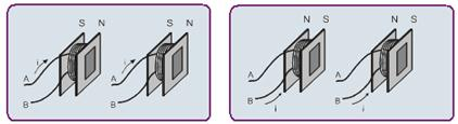
28- I. False — if the body were made of ferromagnetic material, it would always be attracted, regardless of the direction of the current.
II. False — the first figure shows that, when the current flows from A to B, a North pole is formed at the end of the electromagnet facing element “X” — thus, if this element were a permanent magnet with the North end facing the electromagnet, there would be repulsion between them, and the mechanism would not be armed.
III. Correct — when the current flows from B to A, at the end of the electromagnet facing element “X” a South pole is formed — if this element is a permanent magnet with the North pole facing the electromagnet, it is then attracted, arming the mechanism — when the current in the electromagnet is reversed, there is repulsion, disarming the mechanism.
IV. False — if element “X” were another identical coil, connected to the same terminals, the polarizations would be as indicated in the following figure — there would be attraction between the North and South poles of the two coils, arming the mechanism — but when the current was reversed, the poles would also be reversed, continuing the attraction and the mechanism would not be disarmed, remaining armed (figures below).
R-B
29- When the switch is closed, increasing magnetic fluxes (ф) are created in the coils A and B, which, according to the right-hand rule, are leaving the plane that contains them — according to Lenz’s law, this variation in increasing flux generates an induced flux (ф ind ) in the opposite direction, which again, according to the right-hand rule, generates induced currents (i’ and i”) in the coils, both in the clockwise direction, as shown in the following figure.
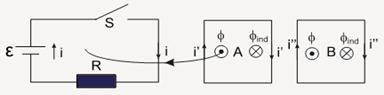
A- A
30- R- E — see theory
31- The loop is crossed by a magnetic field whose direction and sense is given by the right-hand rule (see figure) and
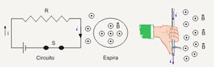
whose intensity depends on the electric current that passes through the circuit, the proximity between the coil and the circuit and the angle between the plane of the coil and the plane of the circuit — the passage of the field through the coil causes a magnetic flux — if this flux is altered, an electric current will appear in the coil, a phenomenon that will occur in three situations:
![]() when turning the switch on or off — immediately after you turn the switch on, the magnetic flux inside the coil is increasing, and when you turn it off, it is decreasing.
when turning the switch on or off — immediately after you turn the switch on, the magnetic flux inside the coil is increasing, and when you turn it off, it is decreasing.
![]() when rotating the coil — when the coil rotates, the magnetic flux inside it is varying (see figures below).
when rotating the coil — when the coil rotates, the magnetic flux inside it is varying (see figures below).
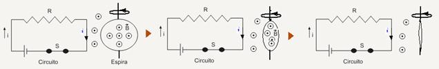
![]() the relative speed between the loop and the circuit increasing or decreasing
the relative speed between the loop and the circuit increasing or decreasing
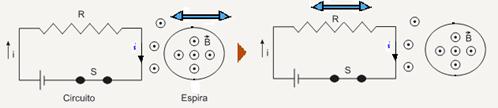
R-C
32- According to the Faraday-Neumann law, the electric current induced in a closed circuit occurs when there is a variation in the magnetic flux through the circuit.
R- And
33- Suppose that the magnet that is descending has the South pole (black color) at the lower end and the North pole (red color) at the upper end, and the lines of the magnetic field that leave the North pole and reach the South pole are schematized in it (figure 1) — let’s consider the tube to be metallic, otherwise there will be no electromagnetic induction — while the magnet descends, the flux of the magnetic field is increased in the region (a) close to the South pole.
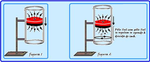
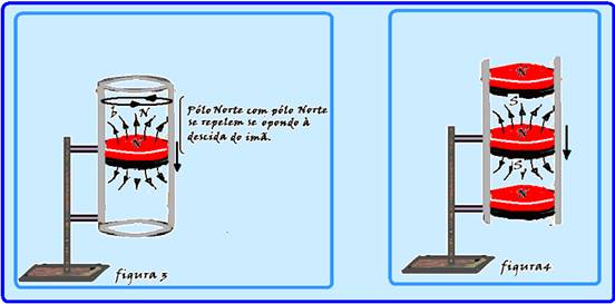
of the magnet, creating an induced electric current that creates a magnetic field and consequently a magnet with a South pole in the upper part that opposes the descent of the magnet (figure 2) — in the same way, while the magnet descends, the flux of the magnetic field is reduced in the region (a) close to the North pole of the magnet, creating an induced electric current that creates a magnetic field and consequently a magnet with a South pole in the lower part that opposes the descent of the magnet (figure 3) — thus, two magnets are created in the metal tube whose poles oppose the descent of the magnet, making it difficult for it to fall (figure 4) and the entire phenomenon described is explained by Lenz’s law — R-B .
34-(PUC-RS)
Please read the information below carefully:
Qualitative laws about electromagnetic induction:
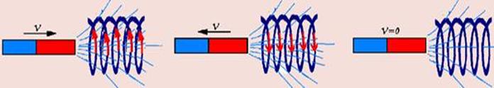
![]() All induced electric current is caused by a variation in the magnetic flux of induction, which will occur if the magnet is approaching or moving away at speed V.
All induced electric current is caused by a variation in the magnetic flux of induction, which will occur if the magnet is approaching or moving away at speed V.
![]() There is no induced current if there is no variation in the magnetic flux of induction, which occurs if the speed of the magnet is zero.
There is no induced current if there is no variation in the magnetic flux of induction, which occurs if the speed of the magnet is zero.
A) False — the greater the speed at which the magnet approaches or moves away from the coil, the greater the intensity of the induced electric current and the higher the galvanometer reading.
D) False — with the magnet at rest there will be flux, but not its variation.
R- B .
35-(UFJF-MG)
The direction of the magnetic field ![]() is given by the right hand rule—thumb rule in the direction of the current.
is given by the right hand rule—thumb rule in the direction of the current.
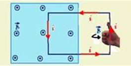
ie the direction and sense of ![]() , which is coming out of the sheet of paper is in the direction of the “closed” hand, which must pass through the coil (see figure) — thus, the current in the coil is in the counterclockwise direction — the induced emf is given by the expression — ε = BLV=0.1.0,6.20=1.2V — R- C .
, which is coming out of the sheet of paper is in the direction of the “closed” hand, which must pass through the coil (see figure) — thus, the current in the coil is in the counterclockwise direction — the induced emf is given by the expression — ε = BLV=0.1.0,6.20=1.2V — R- C .
36-(UNESP-SP)

An electromagnetic brake is a device in which electromagnetic interactions cause a reduction in speed in a moving body, without the need for frictional forces. The experiment described below illustrates how an electromagnetic brake works.
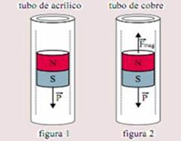
In figure 1, a cylindrical magnet descends in accelerated motion inside a vertical cylindrical acrylic tube, subject only to the action of the weight force.
In figure 2, the same magnet descends in uniform movement inside a vertical, cylindrical copper tube, subject to the action of the weight force and the magnetic force, vertical and upwards, which arises due to the induced electric current that circulates through the copper tube, caused by the movement of the magnet inside it.
In both situations, friction between the magnet and the tubes and air resistance can be disregarded.
Considering the polarity of the magnet, the lines of magnetic induction created by it and the direction of the electric current induced in the copper conducting tube below the magnet, when it descends inside the tube, the alternative that shows a situation consistent with the appearance of a vertical magnetic force upwards in the magnet is the one indicated by the letter
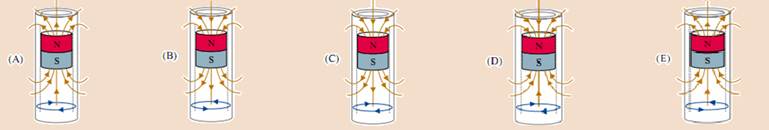
The induction lines of the magnetic field created by the cylindrical magnet leave its north pole and reach its south pole — thus, only alternatives (A) and (E) remain — when moving down inside the copper tube, the cylindrical magnet creates induced electric currents in it that behave as if they were an electromagnet — these electric currents must have directions such that the electromagnet generated by them must prevent the cylindrical magnet from approaching its bottom part, repelling it, and prevent it from moving away from the top part, attracting it (Lenz’s law) — for this to occur, the generated electromagnets must be such that the currents
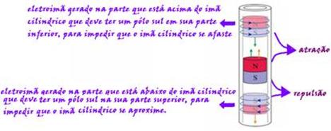
that circulate through it in the copper cylinder must have the directions shown in the figure above and which are provided by the right-hand rule — note that, of the configurations provided, the only one that satisfies is the one shown in figure A — R- A