Pouillet’s Law – EN Receptors
POUILLET’S LAW – RECEPTORS
Receivers – Association of generators with receivers – Pouillet’s Law
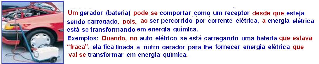
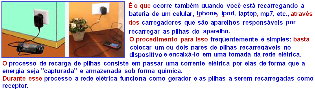
Electrical receiver
A device that converts electrical energy into another form of energy, not exclusively thermal. Examples: electric motors, fans, blenders, refrigerators, stereos, videos, cell phones, computers, etc.

A fan, for example , converts thermal energy into mechanical energy; this conversion, however, is not complete, as part of the energy is inevitably converted into thermal energy.
Characteristic quantities of an electrical receiver
There are two: the first is the counter-electromotive force (E’), a quantity ( measured in volts “1V=1J/C” ) defined as the ratio between the work (W) and the amount of charge (Q) that performs this work inside the receiver and which is the potential difference actually used to produce non-thermal energy; the second is its internal resistance r’.
Schematic representation of a receiver
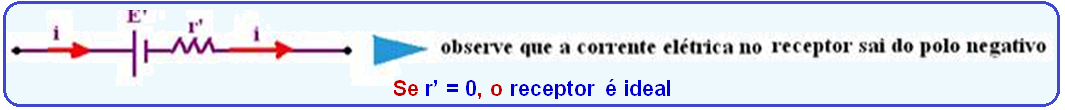
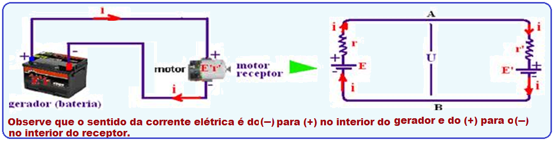
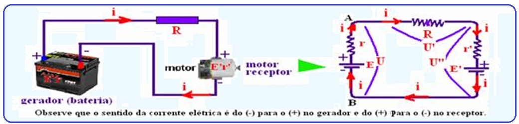
Electrical circuit with a generator powering a receiver
In the circuit shown in the figure, a generator (battery) powers a receiver (motor), establishing a potential difference across it.
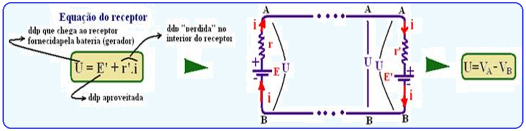
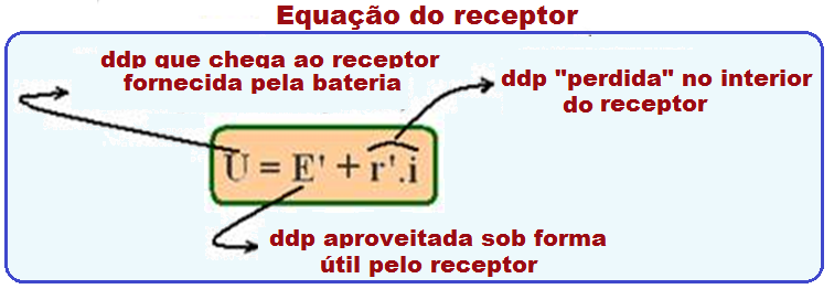
Receiver equation
Consider an electrical receiver (a small electric fan, for example), receiving U = 2 V from a battery (meaning that the motor receives 2J of electrical energy from the battery for every 1C of charge that passes through it).
Suppose that U’ = r’.i = 0.5V (meaning that a portion of electrical energy equal to 0.5J received by the fan, for each 1C of charge that passes through it, is converted into thermal energy , needlessly heating the motor (energy dissipated, lost, wasted).
For the motor (receiver) to produce mechanical energy , there remains E’ = U – r’.i = 2 – 0.5 E’ = 1.5V, which means that an electrical energy of 1.5J is usefully converted into non-thermal energy (mechanical, in this case), for each 1C of charge that passes through the motor (receiver). ![]()
![]()
Like this:
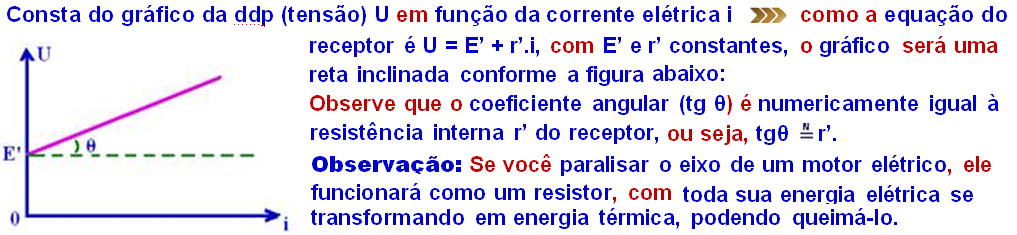
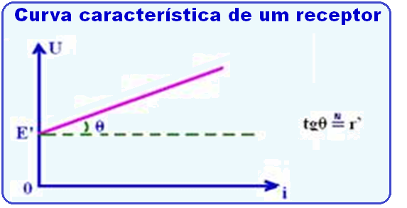
Receiver characteristic curve
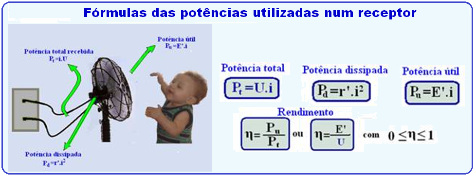
Powers of a receiver (equations)
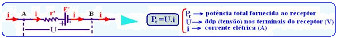
![]() Total power (P t ) corresponds to the total energy received by the receiver from the external source (generator) per unit of time:
Total power (P t ) corresponds to the total energy received by the receiver from the external source (generator) per unit of time: ![]()
 Dissipated power (P d ) refers to the power consumed (“lost”, dissipated, in thermal form) by the internal resistance r’ of the receiver and provided by:
 ![]()
![]()
Useful power (P u ) power used by the receiver for its normal operation, in non-thermal form . ![]()
Example: in a fan, it is the portion of the total energy that is transformed into exclusively mechanical energy, to turn its blades.
![]()
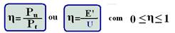
Efficiency (η) of a receiver
The efficiency (η) of a receiver is defined as the ratio between its useful power (P u ) and its total power P t ):
What you should know, information and tips
![]()
![]()
![]()
If you stop the shaft of an electric motor, it will act as a resistor, with all its electrical energy being transformed into thermal energy, which could burn it out.
![]()
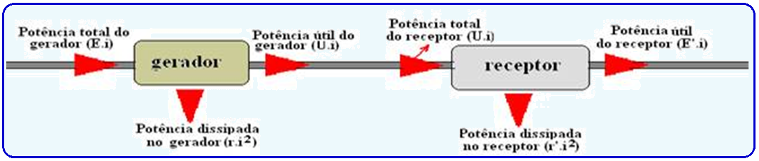
The electrical power that the generator delivers to the receiver is the generator’s useful power (Ui).
For the receiver, this same power represents the total power. Of this total, a portion is useful (E’.i) and the other is dissipated (r’.i 2 ). Observe the diagram below carefully.
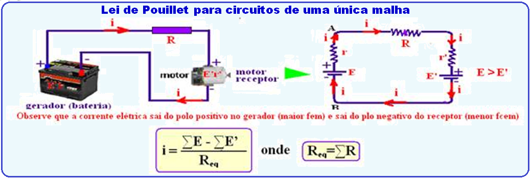
Pouillet’s Law – Single-loop electrical circuit with generators and receivers
Let there be a generator of electromotive force (emf) and internal resistance r, a receiver of counter-electromotive force (fcem) E’ and internal resistance r’ and a resistor of resistance R, associated in series as shown in the figure, constituting a single-mesh electrical circuit.
As they are in series, the intensity of the electric current i is the same in each device.
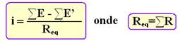
The generator creates at its terminals A and B a ddp (voltage) U that causes a potential rise and that must be equal to the sum of the potential drops caused by the resistor U’ and the receiver U”, that is, U = U’ + U” U = E – ri U’ = Ri U’ = E’ + r’.i E – ri = Ri + E’ + r’.i E – E’=(r + r’ + R).i i=(E – E’)/(r + r’ + R) generalizing in single-mesh circuits: ![]()
![]()
![]()
![]()
![]()
![]()
![]()
![]()
Analyze this example carefully: In the circuit diagram below, determine:
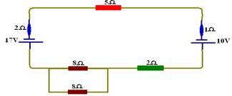
a) the intensity of the electric current in the generator, in the receiver and in the 5Ω resistance.
b) The potential difference at the terminals of the generator, the receiver and the 5Ω resistor.
a) As the direction of the electric current is not specified, it follows the direction of the highest emf, which is that of the generator, where the current leaves through the positive pole.
In this case, the 17V emf is the generator and the current in the circuit is in the counterclockwise direction, since the current comes out of the positive pole of the circuit. The circuit must be transformed into a single-mesh circuit and, thus, the parallel association must be resolved (8/2 = 4Ω).

Applying Pouillet’s law i = (∑E – ∑E’)/∑R = (17 – 10)/(4 + 2 + 1 + 5 + 2) i = 7/14 i = 0.5A , which is the same through all elements of the circuit, as they are in series. ![]()
![]()
![]()
b) Generator U g = E – ri = 17 – 2.0.5 U g = 16V receiver U r = E’ + r’.i = 10 + 1.0.5 U r = 9.5V U 5Ω = Ri = 5.0.5 U 5Ω = 2.5V. ![]()
![]()
![]()
![]()
![]()
![]()
![]()
What you should know, information and tips
![]()
![]()