Capacitors (Capacitors) EN
CAPACITORS (CONDENSERS)
Capacitors ( Condensers )
Capacitor or condenser
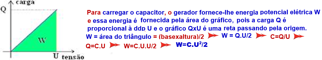
A capacitor or condenser is an electrical device whose function is to store electrical charges and, as a consequence, electrical potential energy.
There are several types of capacitors (cylindrical, spherical or flat), but they are all represented by two parallel, conductive and identical plates, very close to each other and with
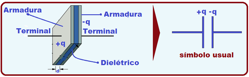
an insulator called a dielectric between them . These plates are called the capacitor’s armature and the dielectric (insulator) between them can be vacuum, air, paper, mica, oil, etc.
Electrifying a capacitor (charging process)
In the figure, the capacitor’s armatures are initially neutral and the potential difference between the plates is zero . Then one of the armatures is connected to the positive pole of an electromotive force generator θ and the other to the negative pole of the same generator.
The armature connected to the negative pole of the generator is charged with negative charges (removing electrons from the top plate) and the one connected to the positive pole of the generator is charged with positive charges (adding electrons to the bottom plate) and as they are charged the potential difference between the plates increases until it equals that of the generator (E) and the
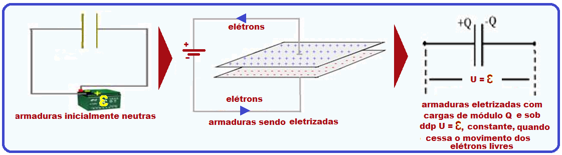
capacitor is charged with voltage U = Ɛ.
By definition, the electric charge (Q) of this capacitor is the value of the charge on the positive plate. Remember that the charges on the positive and negative plates have the same magnitude.
U is the potential difference between the positive and negative plates and Q is the magnitude of the charge on one of the plates.
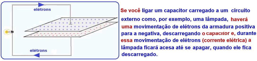
Capacitor discharge process
Capacitance or electrostatic capacity of a capacitor
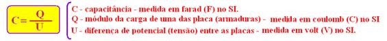
The capacitance or electrostatic capacity of a capacitor represented by the letter C is characteristic of each capacitor, being defined as the ratio between the charge Q (measured in coulomb “C” in SI) stored in the capacitor and the potential difference U (measured in volt “V”, in SI) between the positive and negative armatures, that is:

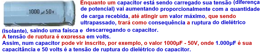
In the International System of Units (SI), capacitance (capacity) is measured in farads, whose symbol is F ; however, as the farad is very large, it is convenient to use submultiples, such as the microfarad (1 μF = 10 -6 F), or the picofarad (1pF = 10 -12 F).
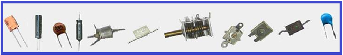
Capacitors are widely used in electronic circuits , where they accumulate electrical charge and consequently electrical energy to later use at an appropriate time , such as in remote controls, cell phones, cordless phones, computers, and stereos.
 microwave ovens, camera flash, etc.
What you should know, information and tips
![]()
![]()
![]()
![]()
Factors that influence the capacitance of a capacitor
![]() As the capacitance of a capacitor is a constant characteristic of it , it depends on some factors specific to each capacitor, which are:
As the capacitance of a capacitor is a constant characteristic of it , it depends on some factors specific to each capacitor, which are:
![]() Area of the armature
Area of the armature ![]() the capacitance C is proportional to the area S of each armature, that is, the larger the area of the armature, the greater the capacitance: C S.
the capacitance C is proportional to the area S of each armature, that is, the larger the area of the armature, the greater the capacitance: C S. ![]()
The thickness (d) of the dielectric is another factor that influences capacitance (they are inversely proportional).
It can be seen that the smaller the distance (d) between the armatures, the greater the capacitance C of the component, that is: C ![]() .(1/d).
.(1/d).
![]() The dielectric is also a determining factor in capacitance , so that its nature influences its value in a directly proportional way, where each dielectric has its characteristic called permittivity of the medium, with symbol ε.
The dielectric is also a determining factor in capacitance , so that its nature influences its value in a directly proportional way, where each dielectric has its characteristic called permittivity of the medium, with symbol ε.
![]() So, we have
So, we have ![]() C= ε.S/d
C= ε.S/d
![]() When the medium is a vacuum, its permittivity is called ε o and is ε o = 8.85.10 -12 F/m.
When the medium is a vacuum, its permittivity is called ε o and is ε o = 8.85.10 -12 F/m.
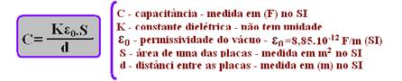
The dielectric constant (K) of a medium is defined as the ratio between the permittivity of that medium ε and the permittivity of the vacuum ε o K = ε/ε o ε = Kε o , which, substituted in C= ε.S/d ![]()
![]()
![]()
C= Kε o .S/d.
What you should know, information and tips
![]() The larger the area (S) of the armature, the greater the capacitance and vice versa.
The larger the area (S) of the armature, the greater the capacitance and vice versa.
![]() The smaller the distance (d) between the armatures, the greater the capacitance and vice versa.
The smaller the distance (d) between the armatures, the greater the capacitance and vice versa.
![]() The greater the dielectric constant K of the insulator (dielectric), the greater the capacitance and vice versa.
The greater the dielectric constant K of the insulator (dielectric), the greater the capacitance and vice versa.
![]()
Capacitor association
Series association of capacitors
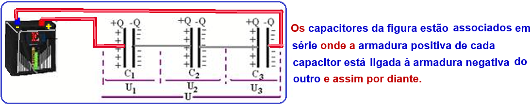
In the charging process, when the capacitors in series are connected to the voltage generator U , the charges leaving one armature will be transferred to the next until the charges of all armatures have the same module, that is, Q 1 = Q 2 = Q 3 = Q.
Note that if the charges are equal and the capacitances are different , the potential difference (voltage) will also be different.
![]()

You can also calculate the equivalent capacitor as C eq = product/sum taken two by two.
Remember that C eq is always less than the capacitance of each of the associated capacitors.
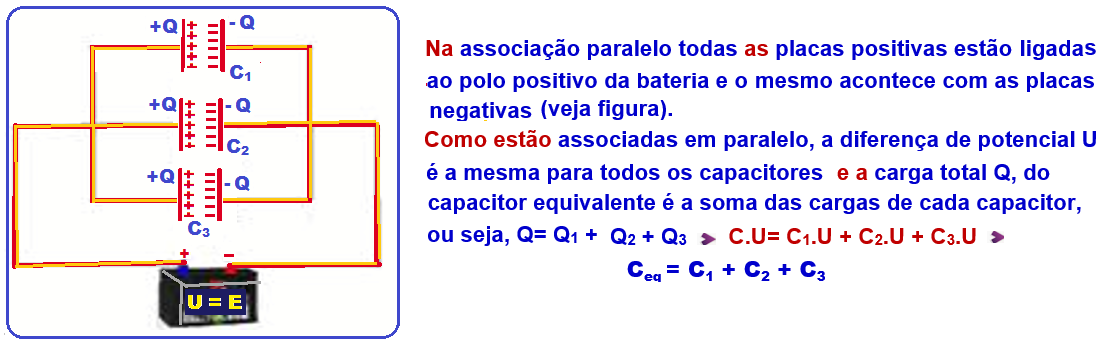
Parallel association of capacitors

Calculation of the equivalent capacitor in a mixed capacitor association
In a mixed association, the calculation of the equivalent capacitor is solved in stages , replacing the capacitors that are in parallel with the equivalent ones , doing the same with those that are in series and so on until reaching a single final equivalent capacitor.
Circuits with capacitors
Remember that when a capacitor is connected to an electrical circuit and is already charged, no more electrical current passes through it , and you just need to remove the branch where it is inserted and solve the circuit.
Pay close attention to these two example exercises:
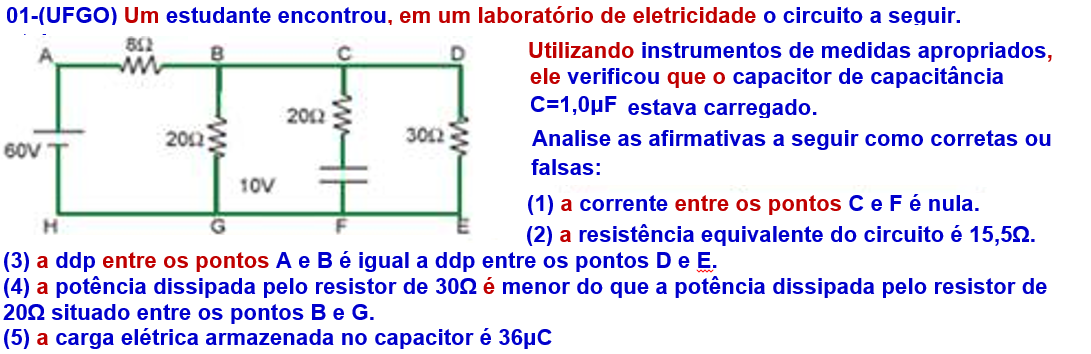
(01) Correct ![]() After the capacitor is charged, no more current flows through the branch where it is inserted.
After the capacitor is charged, no more current flows through the branch where it is inserted.
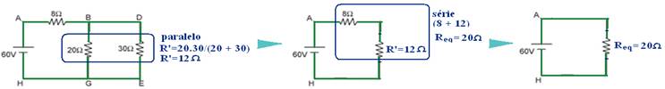
(02) False ![]() Removing the branch where the capacitor is (since it is charged and no current flows through it ) and calculating the equivalent resistance , see the sequence below:
Removing the branch where the capacitor is (since it is charged and no current flows through it ) and calculating the equivalent resistance , see the sequence below: ![]()
(3) False ![]() Look at the sequence below , where you are returning from the sequence above:
Look at the sequence below , where you are returning from the sequence above:
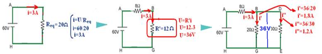
U AB =Ri = 8.3 ![]() U AB = 24V U DE =30.1.2 U DE = 36V.
U AB = 24V U DE =30.1.2 U DE = 36V. ![]()
![]()
(4) Correct ![]() P 30Ω = i”.U = 1.2.36
P 30Ω = i”.U = 1.2.36 ![]() P 30Ω = 43.2W
P 30Ω = 43.2W ![]() P 20 = i’.U = 1.8.36
P 20 = i’.U = 1.8.36 ![]() P 20Ω = 64.8 W. (5) Note that the potential difference across the capacitor terminals (section CF) is the same as across sections BG and DE and is U=36V (they are all in parallel)
P 20Ω = 64.8 W. (5) Note that the potential difference across the capacitor terminals (section CF) is the same as across sections BG and DE and is U=36V (they are all in parallel) ![]() C = Q/U 10 -6 = Q/36
C = Q/U 10 -6 = Q/36 ![]()
![]()
Q = 36.10 -6 C.
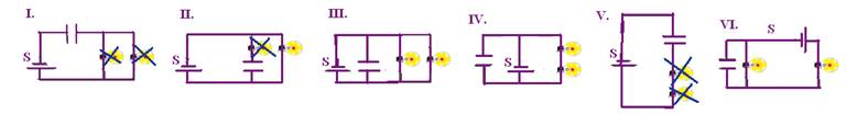
02- (UFLA-MG) In which of the following circuits is it possible to guarantee that , after a very long time interval after closing switch S , all the lamps will be on? Suppose that the battery satisfies the necessary conditions for the lamps to stay on and not burn out .
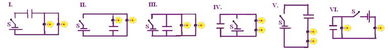 a) I, II, III. b) I, V, VI. c) II, IV, VI. d) III, IV, VI. e) IV, V, VI.
Remember that once the capacitor is charged, it breaks the circuit and no current flows through it or through the section where it is inserted (see figures below)