Exercises on Ammeters and Voltmeters EN
EXERCISES ON AMMETERS AND VOLTMETERS
Entrance exam exercises with commented solutions on
Ammeters and Voltmeters
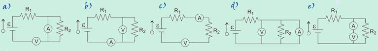
01-(UFB) To determine the resistance R of the circuit below, two measuring devices A and V are used.
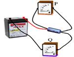
a) Q is a voltmeter
b) P is an ammeter
c) P is an ammeter and Q is a voltmeter
d) Q is an ammeter and P is a voltmeter
e) nothing can be said about P and Q
02-(UFMG-MG) The figure represents a battery, with negligible internal resistance, connected to a lamp L.
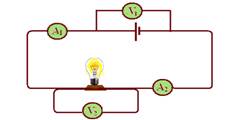
Considering the resistance of the ammeters to be negligible and the resistance of the voltmeters to be very large, and with A 1 and A 2 being the readings of the ammeters and V 1 and V 2 being the readings of the voltmeters, we will have:
a) A 1 = A 2 and V 1 = V 2
b) A1 > A2 and V1 > V2
c) A1 > A2 and V1 > V2
d) A 1 = A 2 and V 1 > V 2
e) A 1 = A 2 and V 2 > V 1
03-(FUVEST-SP) Consider the assembly below, consisting of four equal resistors R, a voltage source F, a current meter A, a voltage meter V and connecting wires. The current meter indicates 8.0A and the voltage meter 2.0V. It can be stated that the total power dissipated in the four resistors is approximately:
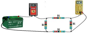
![]()
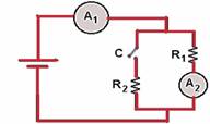
04-(UFRJ-RJ) In the circuit shown in the figure, ammeter A and voltmeter V are ideal.
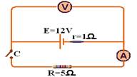
Calculate the ammeter and voltmeter readings:
a) with key C open
b) with key C closed
05-(UFB) In the following circuits, determine the indications provided by the meters, both ideal:
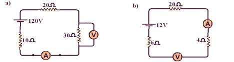
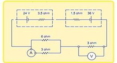
06-(UFBA) The following figure represents an electrical circuit consisting of an ideal voltmeter (V) and an ammeter (A), five resistors and a battery. The battery supplies a voltage of 12.0V and the voltmeter registers 6.0V.
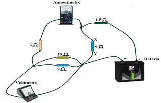
a) What is the reading on the ammeter?
b) What is the potential difference across the 1.5Ω resistor?
c) What is the power dissipated by the resistor located between X and Y?
07-(UFRJ) The diagram in the figure shows part of a direct current electrical circuit. The ammeter always measures a current of 2 A and the resistors are each 1Ω.
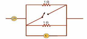
The voltmeter is connected in parallel with one of the resistors.
a) Calculate the voltmeter reading with the switch open.
b) Calculate the voltmeter reading with the switch closed.
08-(UNESP-SP) In the circuit in the figure, the source is a battery with emf E=12V, the resistor has resistance R=1,000Ω. V represents a voltmeter and A an ammeter.
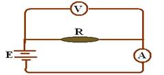
Determine the reading of these meters:
a) under ideal conditions, that is, assuming that the wires and the ammeter have no electrical resistance and that the electrical resistance of the voltmeter is infinite.
b) in real conditions, in which the electrical resistances of the battery, ammeter and voltmeter are r=1.0Ω, R A =50Ω and R V =10,000Ω, respectively, disregarding only the resistance of the connecting wires.
09-(FUVEST-SP) In the circuit shown, E=8V, r=100Ω and R=1,200Ω.

a) What is the reading on ammeter A?
b) What is the reading on the voltmeter V?
10-(FUVEST-SP) In the circuit shown, the ammeter and voltmeter are ideal. The voltmeter reads 1.5V when switch K is open.
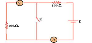
By closing switch K, the ammeter will mark:
a) 0mA
b) 7.5mA
c) 15mA
d) 100mA
e) 200mA
11-(ITA-SP) In the circuit drawn below, there are two batteries of 1.5 V each, with negligible internal resistance, connected in series, supplying current to three resistors with the indicated values. A voltmeter and an ammeter with internal resistances, respectively, very high and very low, are also connected to the circuit.
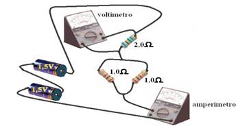
What are the readings of these instruments?
12-(UFF-RJ) In the circuit shown in the figure, the power supply is provided by a battery with an emf equal to 1.5 V and negligible internal resistance; the current (ammeter A) and voltage (voltmeter V) meters are ideal.
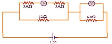
In this situation, the ammeter and voltmeter readings are, respectively:
a) 0.05 A and 0.60 V
b) 0.10 A and 0.90 V
c) 0.15 A and 0.90 V
d) 0.20 A and 0.60 V
e) 0.30 A and 0.30 V
13-(UNICAMP-SP) In the circuit shown in the figure, A is an ammeter with zero resistance and V is a voltmeter with infinite resistance. The internal resistance of the battery is zero.
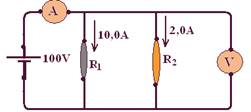
a) What is the intensity of the current measured by the ammeter?
b) What is the voltage measured by the voltmeter?
c) What are the values of the resistances R 1 and R 2 ?
d) What is the power supplied by the battery?
14-(Fatec-SP) In the circuit, ammeter A 1 indicates a current of 200 mA.
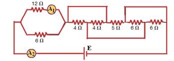
According to the diagram, determine the reading of the ammeter A 2 and the emf E of the generator.
15- (PUC-SP) In the circuit shown in the figure, two identical batteries with an electromotive force of 1.5 V are associated with three resistors: R 1 of 1.0 Ω, R 2 of unknown resistance and R 3 of 2.0 Ω. For the assembly shown, the ideal ammeter reading is 1.2 A and the voltmeter, placed in parallel to R 3, is ideal.
The resistance value of resistor R 2 , in ohms, and the voltmeter reading, in volts, are respectively equal to
a) 1.0 and 2.4
b) 2.0 and 0.8
c) 2.0 and 2.4
d) 1.0 and 0.8
e) 1.2 and 2.4
16-(UFRJ-RJ) The circuit in figure 1 shows an ideal battery that maintains a potential difference of 12 V between its terminals, an ammeter also ideal and two lit lamps with resistances R 1 and R 2 . In this case, the ammeter indicates a current of intensity 1.0 A.
In the situation shown in figure 2, the resistance lamp R‚ remains on and the other is burnt out. In this new situation, the ammeter indicates a current of intensity 0.40 A.
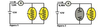
Calculate the resistances R 1 and R 2 .
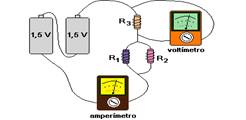
17-(UNIFESP-SP) The experimental setup represented in the figure is intended for the study of a simple electrical circuit.
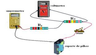
a) Using conventional symbols for each component, schematically represent this circuit.
b) Knowing that R 1 = 100 Ω and R 2 = 200 Ω and that two batteries with an electromotive force of 1.5 V each are placed in series in the battery holder, determine the readings on the ammeter and voltmeter when the switch is closed. (Assume that the internal resistances of the batteries, connecting wires and meters do not interfere with these readings.)
18- (UFC-CE)) In the circuit shown below, A 1 and A 2 are ideal ammeters. Turning on switch C, it is observed that:
a) the reading of A 1 and the reading of A 2 do not change.
b) the reading of A 1 decreases and the reading of A 2 increases.
c) the reading of A 1 does not change and the reading of A 2 decreases.
d) the reading of A 1 increases and the reading of A 2 decreases.
e) the reading of A 1 increases and the reading of A 2 does not change.
19-(UFF-RJ) The ends of two identical conducting cylinders, with resistance R, are connected, by wires of negligible resistance, to the terminals of a source of electromotive force E = 12 V and internal resistance r = 0.50 Ω, as shown in the following diagram. An ideal ammeter A is connected to one of the branches.
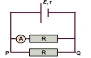
Knowing that the ammeter gives a reading equal to 2.0 A, determine:
a) the difference in electrical potential between points P and Q, identified in the figure
b) the electrical resistance R of the cylinder
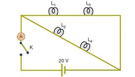
20- (MACK-SP) Four lamps, associated according to the diagram, have the following nominal inscriptions:
L 1 : (10 W, 20 V) L 2 : (20 W, 20 V) L 3 : (5 W, 10 V) L 4 : (10 W, 10 V)
When we turn on the K switch, we will observe that:
a) no lamp will “burn out” and the ideal ammeter will indicate the passage of a current of intensity 1 A
b) no lamp will “burn out” and the ideal ammeter will indicate the passage of a current of intensity 4.5 A
c) none of the lamps will light up, as they were connected outside of the manufacturer’s specifications
d) lamps L 1 and L 3 will “burn out”
e) lamps L 2 and L 4 will “burn out”
21-(UNESP-SP) A student uses the measurements of a voltmeter V and an ammeter A to calculate the electrical resistance of a resistor and the power dissipated in it. The current and voltage measurements were performed using the circuit in the figure.
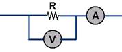
The ammeter indicated 3 mA and the voltmeter 10 V. Carefully, he remembered that the voltmeter is not ideal and that it is necessary to consider the value of the internal resistance of the meter to calculate the value of the resistance R. If the specification for the internal resistance of the device is 10 kΩ, calculate
a) the value of resistance R obtained by the student.
b) the power dissipated in the resistor.
22-(UFSCAR-SP) In the circuit below, ammeters A 1 and A 2 display, respectively, currents i 1 and i 2 :

The currents i 1 and i 2 are:
a) i 1 = 4.25.E/R; i 2 =E/3R
b) i 1 = 4E/R; i 2 =E/R
c) i 1 = E/4.25R; i 2 = E/3R
d) i 1 = 4.25E/R; i 2 = 3.E/R
e) i 1 = E/R; i 2 = 0.25. E/R
23-(UFMG-MG) Observe this circuit, consisting of three resistors of the same resistance R; an ammeter A; a battery ε; and a switch S:
Consider that the internal resistance of the battery and the ammeter are negligible and that the resistors are ohmic. With switch S initially off, it is observed that the ammeter indicates an electric current I.
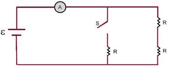
Based on this information, it is CORRECT to state that, when switch S is turned on, the ammeter begins to indicate an electric current
![]()
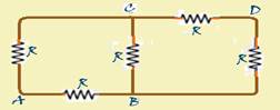
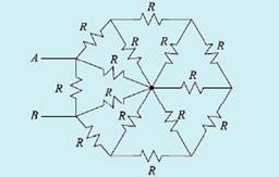
24-(UFMS-MS) In the circuit below, each resistor has resistance (R).
Consider the alternatives:
I. The equivalent resistance between A and B is (5/8)R.
II. The equivalent resistance between A and C is (5/8)R
III. The equivalent resistance between A and D is (R)
IV. The equivalent resistance between B and C is (1/2)R
V. The equivalent resistance between C and D is (5/8)R
It is correct to state that:
a) only statement I is correct
b) only statements I and II are correct
c) only statement III is correct
d) only statements IV and V are correct
e) all are correct
25-(UEG-GO) A simple circuit consists only of a battery (B) and a light bulb (L). With this electrical circuit, a student set up four different connections, with the same power meter.
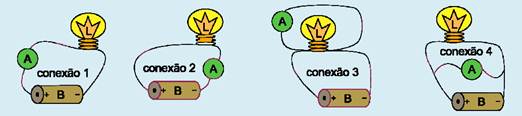
intensity of electric current, known as an ammeter (A). After the assemblies, as shown in the figure above, the student presented versions of the connections made. In which of these versions will the ammeter provide the real reading of the current intensity in the circuit?
a) Connection 1 presents a correct way to read the electric current in a circuit; in this case, it was decided to place the ammeter on the left side of the battery.
b) Connection 2 provides a lower reading than connection 1, since part of the electric current has dissipated as it travels through the entire circuit.
c) Connection 3 is better than connections 1 and 2, as this procedure meant that only the reading of the electric current flowing through the lamp was measured.
d) Connection 4 is almost identical to connection 3 and will therefore provide the actual reading of the electric current flowing through the bulb and also through the battery.
26-(UFRGS-RS) Voltmeters and ammeters are the most common instruments for electrical measurements. Obviously, to obtain correct measurements, these instruments must be connected properly. In addition, they can be damaged if they are connected incorrectly to the circuit.
Suppose you want to measure the potential difference to which resistor R2 in the following circuit is subjected, as well as the electric current that runs through it.
Indicate the figure that represents the correct connection of the voltmeter (V) and ammeter (A) to the circuit to perform the desired measurements.
27-(UPE-PE)


In the electrical circuit below, two identical generators are represented, with E = 12 V and r = 1Ω. The ammeter and the voltmeter
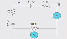
are ideal. Analyze the following propositions and conclude.
( ) The ammeter reading is 2A.
( ) The voltmeter reading is 10 V.
( ) The equivalent resistance of the circuit is 12Ω.
( ) The power dissipated in the 10Ω resistor is 40 W.
( ) The generator efficiency between points C and B is approximately 83.33%.
28-(UNIFEI-MG)


Which of the two setups shown in the figure below should be used to simultaneously measure the voltage drop across a resistance R and the current passing through it if:
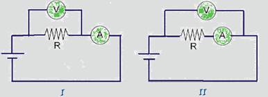
a) R = 4.7 Ω
b) R = 2.2 MΩ
29-(UFRJ-RJ) An ideal battery, an ammeter with an internal resistance of 100 Ω and a resistor with a resistance of 1,400 Ω are connected in series in an initially open circuit with terminals a and b, as shown in the following figure.
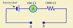
When terminals a and b are connected by a wire of negligible resistance, closing the circuit, a current of 1.00 mA is established in the ammeter. When terminals a and b are connected by a resistor, closing the circuit, a current of 0.20 mA is established in the ammeter.
Calculate the resistance of this resistor.
30-(MACKENZIE-SP) A certain student has a voltmeter and an ammeter, both ideal, an electric generator ( battery ), with an internal resistance of 4.5Ω, and an incandescent lamp with the following nominal inscriptions: 1.0W — 9.0V. In order for these devices to be correctly associated, providing the lamp with the greatest possible brightness, without “burning it”, the scheme that should be used is the one illustrated in _________ and the electromotive force of the generator should be ______.
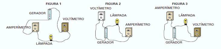
The gaps in the previous text are correctly filled in with the following statements:
a) FIGURE 1; 9.5V
b) FIGURE 2; 9.5V
c) FIGURE 3; 9.5V
d) FIGURE 2; 9.0V
e) FIGURE 3; 9.0V
31-(IME-RJ)

The value of equivalent resistance between terminals A and B of the circuit shown in the figure below is:
a) R/2
b) 6R/7
c) 6R/13
d) 16R/29
e) 15R/31
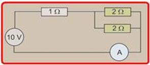
32-(PUC-RJ)

Calculate the current in amps measured on the ammeter (A) in the circuit shown in the figure.
![]()
33-(MACKENZIE-SP)

In the electrical circuit shown below, the electric generator has negligible electrical resistance. Both the ammeter and the voltmeter are considered ideal. The lamps illustrated are identical and have the nominal information
(1 W — 10 V). After closing switch K, the ammeter and voltmeter will indicate, respectively,
a) 50 mA and 1.25 V
b) 25 mA and 1.25 V
c) 50 mA and 2.50 V
d) 25 mA and 2.50 V
e) 75 mA and 5.00 V
34-(MACKENZIE-SP-012)

In the Physics laboratory, the electrical circuit is assembled next to it, with an ideal generator and the switches (keys) K 1 , K 2 and K 3 . With
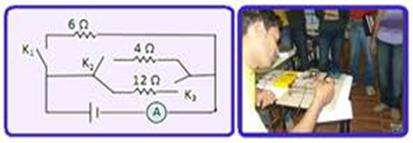
only the switch K 1 closed, the ideal ammeter indicates the passage of electric current of intensity 5 A. Closing all
the switches, the power generated by the generator is
a) 300 W
b) 350 W
c) 400 W
d) 450 W
e) 500 W
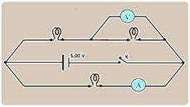
35-(UENP-PR)

From the electrical circuit below, select the alternative that indicates, respectively, the reading of ammeter A (in A) and that of
voltmeter (in V).
a) 0.2 and 0.9
b) 0.4 and 1.2
c) 0.6 and 4.8
d) 0.8 and 3.6
e) 1.0 and 9.0
Check the answer key and commented resolution
EXERCISES ON AMMETERS AND VOLTMETERS
Entrance exam exercises with commented solutions on
Ammeters and Voltmeters
01-(UFB) To determine the resistance R of the circuit below, two measuring devices A and V are used.
a) Q is a voltmeter
b) P is an ammeter
c) P is an ammeter and Q is a voltmeter
d) Q is an ammeter and P is a voltmeter
e) nothing can be said about P and Q
02-(UFMG-MG) The figure represents a battery, with negligible internal resistance, connected to a lamp L.
Considering the resistance of the ammeters to be negligible and the resistance of the voltmeters to be very large, and with A 1 and A 2 being the readings of the ammeters and V 1 and V 2 being the readings of the voltmeters, we will have:
a) A 1 = A 2 and V 1 = V 2
b) A1 > A2 and V1 > V2
c) A1 > A2 and V1 > V2
d) A 1 = A 2 and V 1 > V 2
e) A 1 = A 2 and V 2 > V 1
03-(FUVEST-SP) Consider the assembly below, consisting of four equal resistors R, a voltage source F, a current meter A, a voltage meter V and connecting wires. The current meter indicates 8.0A and the voltage meter 2.0V. It can be stated that the total power dissipated in the four resistors is approximately:
![]()
04-(UFRJ-RJ) In the circuit shown in the figure, ammeter A and voltmeter V are ideal.
Calculate the ammeter and voltmeter readings:
a) with key C open
b) with key C closed
05-(UFB) In the following circuits, determine the indications provided by the meters, both ideal:
06-(UFBA) The following figure represents an electrical circuit consisting of an ideal voltmeter (V) and an ammeter (A), five resistors and a battery. The battery supplies a voltage of 12.0V and the voltmeter registers 6.0V.
a) What is the reading on the ammeter?
b) What is the potential difference across the 1.5Ω resistor?
c) What is the power dissipated by the resistor located between X and Y?
07-(UFRJ) The diagram in the figure shows part of a direct current electrical circuit. The ammeter always measures a current of 2 A and the resistors are each 1Ω.
The voltmeter is connected in parallel with one of the resistors.
a) Calculate the voltmeter reading with the switch open.
b) Calculate the voltmeter reading with the switch closed.
08-(UNESP-SP) In the circuit in the figure, the source is a battery with emf E=12V, the resistor has resistance R=1,000Ω. V represents a voltmeter and A an ammeter.
Determine the reading of these meters:
a) under ideal conditions, that is, assuming that the wires and the ammeter have no electrical resistance and that the electrical resistance of the voltmeter is infinite.
b) in real conditions, in which the electrical resistances of the battery, ammeter and voltmeter are r=1.0Ω, R A =50Ω and R V =10,000Ω, respectively, disregarding only the resistance of the connecting wires.
09-(FUVEST-SP) In the circuit shown, E=8V, r=100Ω and R=1,200Ω.
a) What is the reading on ammeter A?
b) What is the reading on the voltmeter V?
10-(FUVEST-SP) In the circuit shown, the ammeter and voltmeter are ideal. The voltmeter reads 1.5V when switch K is open.
By closing switch K, the ammeter will mark:
a) 0mA
b) 7.5mA
c) 15mA
d) 100mA
e) 200mA
11-(ITA-SP) In the circuit drawn below, there are two batteries of 1.5 V each, with negligible internal resistance, connected in series, supplying current to three resistors with the indicated values. A voltmeter and an ammeter with internal resistances, respectively, very high and very low, are also connected to the circuit.
What are the readings of these instruments?
12-(UFF-RJ) In the circuit shown in the figure, the power supply is provided by a battery with an emf equal to 1.5 V and negligible internal resistance; the current (ammeter A) and voltage (voltmeter V) meters are ideal.
In this situation, the ammeter and voltmeter readings are, respectively:
a) 0.05 A and 0.60 V
b) 0.10 A and 0.90 V
c) 0.15 A and 0.90 V
d) 0.20 A and 0.60 V
e) 0.30 A and 0.30 V
13-(UNICAMP-SP) In the circuit shown in the figure, A is an ammeter with zero resistance and V is a voltmeter with infinite resistance. The internal resistance of the battery is zero.
a) What is the intensity of the current measured by the ammeter?
b) What is the voltage measured by the voltmeter?
c) What are the values of the resistances R 1 and R 2 ?
d) What is the power supplied by the battery?
14-(Fatec-SP) In the circuit, ammeter A 1 indicates a current of 200 mA.
According to the diagram, determine the reading of the ammeter A 2 and the emf E of the generator.
15- (PUC-SP) In the circuit shown in the figure, two identical batteries with an electromotive force of 1.5 V are associated with three resistors: R 1 of 1.0 Ω, R 2 of unknown resistance and R 3 of 2.0 Ω. For the assembly shown, the ideal ammeter reading is 1.2 A and the voltmeter, placed in parallel to R 3, is ideal.
The resistance value of resistor R 2 , in ohms, and the voltmeter reading, in volts, are respectively equal to
a) 1.0 and 2.4
b) 2.0 and 0.8
c) 2.0 and 2.4
d) 1.0 and 0.8
e) 1.2 and 2.4
16-(UFRJ-RJ) The circuit in figure 1 shows an ideal battery that maintains a potential difference of 12 V between its terminals, an ammeter also ideal and two lit lamps with resistances R 1 and R 2 . In this case, the ammeter indicates a current of intensity 1.0 A.
In the situation shown in figure 2, the resistance lamp R‚ remains on and the other is burnt out. In this new situation, the ammeter indicates a current of intensity 0.40 A.
Calculate the resistances R 1 and R 2 .
17-(UNIFESP-SP) The experimental setup represented in the figure is intended for the study of a simple electrical circuit.
a) Using conventional symbols for each component, schematically represent this circuit.
b) Knowing that R 1 = 100 Ω and R 2 = 200 Ω and that two batteries with an electromotive force of 1.5 V each are placed in series in the battery holder, determine the readings on the ammeter and voltmeter when the switch is closed. (Assume that the internal resistances of the batteries, connecting wires and meters do not interfere with these readings.)
18- (UFC-CE)) In the circuit shown below, A 1 and A 2 are ideal ammeters. Turning on switch C, it is observed that:
a) the reading of A 1 and the reading of A 2 do not change.
b) the reading of A 1 decreases and the reading of A 2 increases.
c) the reading of A 1 does not change and the reading of A 2 decreases.
d) the reading of A 1 increases and the reading of A 2 decreases.
e) the reading of A 1 increases and the reading of A 2 does not change.
19-(UFF-RJ) The ends of two identical conducting cylinders, with resistance R, are connected, by wires of negligible resistance, to the terminals of a source of electromotive force E = 12 V and internal resistance r = 0.50 Ω, as shown in the following diagram. An ideal ammeter A is connected to one of the branches.
Knowing that the ammeter gives a reading equal to 2.0 A, determine:
a) the difference in electrical potential between points P and Q, identified in the figure
b) the electrical resistance R of the cylinder
20- (MACK-SP) Four lamps, associated according to the diagram, have the following nominal inscriptions:
L 1 : (10 W, 20 V) L 2 : (20 W, 20 V) L 3 : (5 W, 10 V) L 4 : (10 W, 10 V)
When we turn on the K switch, we will observe that:
a) no lamp will “burn out” and the ideal ammeter will indicate the passage of a current of intensity 1 A
b) no lamp will “burn out” and the ideal ammeter will indicate the passage of a current of intensity 4.5 A
c) none of the lamps will light up, as they were connected outside of the manufacturer’s specifications
d) lamps L 1 and L 3 will “burn out”
e) lamps L 2 and L 4 will “burn out”
21-(UNESP-SP) A student uses the measurements of a voltmeter V and an ammeter A to calculate the electrical resistance of a resistor and the power dissipated in it. The current and voltage measurements were performed using the circuit in the figure.
The ammeter indicated 3 mA and the voltmeter 10 V. Carefully, he remembered that the voltmeter is not ideal and that it is necessary to consider the value of the internal resistance of the meter to calculate the value of the resistance R. If the specification for the internal resistance of the device is 10 kΩ, calculate
a) the value of resistance R obtained by the student.
b) the power dissipated in the resistor.
22-(UFSCAR-SP) In the circuit below, ammeters A 1 and A 2 display, respectively, currents i 1 and i 2 :
The currents i 1 and i 2 are:
a) i 1 = 4.25.E/R; i 2 =E/3R
b) i 1 = 4E/R; i 2 =E/R
c) i 1 = E/4.25R; i 2 = E/3R
d) i 1 = 4.25E/R; i 2 = 3.E/R
e) i 1 = E/R; i 2 = 0.25. E/R
23-(UFMG-MG) Observe this circuit, consisting of three resistors of the same resistance R; an ammeter A; a battery ε; and a switch S:
Consider that the internal resistance of the battery and the ammeter are negligible and that the resistors are ohmic. With switch S initially off, it is observed that the ammeter indicates an electric current I.
Based on this information, it is CORRECT to state that, when switch S is turned on, the ammeter begins to indicate an electric current
![]()
24-(UFMS-MS) In the circuit below, each resistor has resistance (R).
Consider the alternatives:
I. The equivalent resistance between A and B is (5/8)R.
II. The equivalent resistance between A and C is (5/8)R
III. The equivalent resistance between A and D is (R)
IV. The equivalent resistance between B and C is (1/2)R
V. The equivalent resistance between C and D is (5/8)R
It is correct to state that:
a) only statement I is correct
b) only statements I and II are correct
c) only statement III is correct
d) only statements IV and V are correct
e) all are correct
25-(UEG-GO) A simple circuit consists only of a battery (B) and a light bulb (L). With this electrical circuit, a student set up four different connections, with the same power meter.
intensity of electric current, known as an ammeter (A). After the assemblies, as shown in the figure above, the student presented versions of the connections made. In which of these versions will the ammeter provide the real reading of the current intensity in the circuit?
a) Connection 1 presents a correct way to read the electric current in a circuit; in this case, it was decided to place the ammeter on the left side of the battery.
b) Connection 2 provides a lower reading than connection 1, since part of the electric current has dissipated as it travels through the entire circuit.
c) Connection 3 is better than connections 1 and 2, as this procedure meant that only the reading of the electric current flowing through the lamp was measured.
d) Connection 4 is almost identical to connection 3 and will therefore provide the actual reading of the electric current flowing through the bulb and also through the battery.
26-(UFRGS-RS) Voltmeters and ammeters are the most common instruments for electrical measurements. Obviously, to obtain correct measurements, these instruments must be connected properly. In addition, they can be damaged if they are connected incorrectly to the circuit.
Suppose you want to measure the potential difference to which resistor R2 in the following circuit is subjected, as well as the electric current that runs through it.
Indicate the figure that represents the correct connection of the voltmeter (V) and ammeter (A) to the circuit to perform the desired measurements.
27-(UPE-PE)
In the electrical circuit below, two identical generators are represented, with E = 12 V and r = 1Ω. The ammeter and the voltmeter
are ideal. Analyze the following propositions and conclude.
( ) The ammeter reading is 2A.
( ) The voltmeter reading is 10 V.
( ) The equivalent resistance of the circuit is 12Ω.
( ) The power dissipated in the 10Ω resistor is 40 W.
( ) The generator efficiency between points C and B is approximately 83.33%.
28-(UNIFEI-MG)
Which of the two setups shown in the figure below should be used to simultaneously measure the voltage drop across a resistance R and the current passing through it if:
a) R = 4.7 Ω
b) R = 2.2 MΩ
29-(UFRJ-RJ) An ideal battery, an ammeter with an internal resistance of 100 Ω and a resistor with a resistance of 1,400 Ω are connected in series in an initially open circuit with terminals a and b, as shown in the following figure.
When terminals a and b are connected by a wire of negligible resistance, closing the circuit, a current of 1.00 mA is established in the ammeter. When terminals a and b are connected by a resistor, closing the circuit, a current of 0.20 mA is established in the ammeter.
Calculate the resistance of this resistor.
30-(MACKENZIE-SP) A certain student has a voltmeter and an ammeter, both ideal, an electric generator ( battery ), with an internal resistance of 4.5Ω, and an incandescent lamp with the following nominal inscriptions: 1.0W — 9.0V. In order for these devices to be correctly associated, providing the lamp with the greatest possible brightness, without “burning it”, the scheme that should be used is the one illustrated in _________ and the electromotive force of the generator should be ______.
The gaps in the previous text are correctly filled in with the following statements:
a) FIGURE 1; 9.5V
b) FIGURE 2; 9.5V
c) FIGURE 3; 9.5V
d) FIGURE 2; 9.0V
e) FIGURE 3; 9.0V
31-(IME-RJ)
The value of equivalent resistance between terminals A and B of the circuit shown in the figure below is:
a) R/2
b) 6R/7
c) 6R/13
d) 16R/29
e) 15R/31
32-(PUC-RJ)
Calculate the current in amps measured on the ammeter (A) in the circuit shown in the figure.
![]()
33-(MACKENZIE-SP)
In the electrical circuit shown below, the electric generator has negligible electrical resistance. Both the ammeter and the voltmeter are considered ideal. The lamps illustrated are identical and have the nominal information
(1 W — 10 V). After closing switch K, the ammeter and voltmeter will indicate, respectively,
a) 50 mA and 1.25 V
b) 25 mA and 1.25 V
c) 50 mA and 2.50 V
d) 25 mA and 2.50 V
e) 75 mA and 5.00 V
34-(MACKENZIE-SP-012)
In the Physics laboratory, the electrical circuit is assembled next to it, with an ideal generator and the switches (keys) K 1 , K 2 and K 3 . With
only the switch K 1 closed, the ideal ammeter indicates the passage of electric current of intensity 5 A. Closing all
the switches, the power generated by the generator is
a) 300 W
b) 350 W
c) 400 W
d) 450 W
e) 500 W
35-(UENP-PR)
From the electrical circuit below, select the alternative that indicates, respectively, the reading of ammeter A (in A) and that of
voltmeter (in V).
a) 0.2 and 0.9
b) 0.4 and 1.2
c) 0.6 and 4.8
d) 0.8 and 3.6
e) 1.0 and 9.0